The May 2024 issue of IEEE Spectrum is here!

For IEEE Members
Ieee spectrum, follow ieee spectrum, support ieee spectrum, enjoy more free content and benefits by creating an account, saving articles to read later requires an ieee spectrum account, the institute content is only available for members, downloading full pdf issues is exclusive for ieee members, downloading this e-book is exclusive for ieee members, access to spectrum 's digital edition is exclusive for ieee members, following topics is a feature exclusive for ieee members, adding your response to an article requires an ieee spectrum account, create an account to access more content and features on ieee spectrum , including the ability to save articles to read later, download spectrum collections, and participate in conversations with readers and editors. for more exclusive content and features, consider joining ieee ., join the world’s largest professional organization devoted to engineering and applied sciences and get access to all of spectrum’s articles, archives, pdf downloads, and other benefits. learn more →, join the world’s largest professional organization devoted to engineering and applied sciences and get access to this e-book plus all of ieee spectrum’s articles, archives, pdf downloads, and other benefits. learn more →, access thousands of articles — completely free, create an account and get exclusive content and features: save articles, download collections, and talk to tech insiders — all free for full access and benefits, join ieee as a paying member., terrapower’s nuclear reactor could power the 21st century, the traveling-wave reactor and other advanced reactor designs could solve our fossil fuel dependency.

Jump to Articles in this Section
- Fuel Cells Finally Find a Killer App: Carbon Capture
- This Power Plant Runs on CO 2
- Cement, Steel, and Natural Gas Are Major Greenhouse Gas Emitters, Too
Table tennis isn’t meant to be played at Mach 2. At twice the speed of sound, the ping-pong ball punches a hole straight through the paddle. The engineers at TerraPower, a startup that has designed an advanced nuclear power reactor, use a pressurized-air cannon to demonstrate that very point to visitors. The stunt vividly illustrates a key concept in nuclear fission: Small objects traveling at high speed can have a big impact when they hit something seemingly immovable.
And perhaps there is a larger point being made here, too—one about a small and fast-moving startup having a big impact on the electric-power industry, which for many years also seemed immovable.
In a world defined by climate change , many experts hope that the electricity grid of the future will be powered entirely by solar, wind, and hydropower. Yet few expect that clean energy grid to manifest soon enough to bring about significant cuts in greenhouse gases within the next few decades. Solar- and wind-generated electricity are growing faster than any other category; nevertheless, together they accounted for less than 2 percent of the world’s primary energy consumption in 2015, according to the Renewable Energy Policy Network for the 21st Century.
To build a bridge to that clean green grid of the future, many experts say we must depend on fission power. Among carbon-free power sources, only nuclear fission reactors have a track record of providing high levels of power, consistently and reliably, independent of weather and regardless of location.
Yet commercial nuclear reactors have barely changed since the first plants were commissioned halfway through the 20th century. Now, a significant fraction of the world’s 447 operable power reactors are showing their age and shortcomings, and after the Fukushima Daiichi disaster in Japan seven years ago, nuclear energy is in a precarious position. Between 2005 and 2015, the world share of nuclear in energy consumption fell from 5.73 to 4.44 percent . The abandonment of two giant reactor projects in South Carolina in the United States and the spiraling costs of completing the Hinkley Point C reactor in the United Kingdom, now projected to cost an eye-watering £20.3 billion (US $27.4 billion), have added to the malaise.
Elsewhere, there is some nuclear enthusiasm: China’s 38 reactors have a total of 33 gigawatts of nuclear capacity, and the country has plans to add an additional 58 GW by 2024. At the moment, some 50 power reactors are under construction worldwide. These reactors, plus an additional 110 that are planned, would contribute some 160 GW to the world’s grids, and avoid the emission of some 500 million metric tons of carbon dioxide every year. To get that kind of cut in greenhouse gases in the transportation sector, you’d have to junk more than 100 million cars , or roughly all the passenger cars in France, Germany, and the United Kingdom .
Against this backdrop, several U.S. startups are pushing new reactor designs they say will address nuclear’s major shortcomings. In Cambridge, Mass., a startup called Transatomic Power is developing a reactor that runs on a liquid uranium fluoride–lithium fluoride mixture. In Denver, Gen4 Energy is designing a smaller, modular reactor that could be deployed quickly in remote sites.
In this cluster of nuclear startups, TerraPower, based in Bellevue, Wash., stands out because it has deep pockets and a connection to nuclear-hungry China. Development of the reactor is being funded in part by Bill Gates, who serves as the company’s chairman. And to prove that its design is viable, TerraPower is poised to break ground on a test reactor next year in cooperation with the China National Nuclear Corp.
To reduce its coal dependence, China is racing to add over 250 GW of capacity by 2020 from renewables and nuclear. TerraPower’s president, Chris Levesque, sees an opening there for a nuclear reactor that is safer and more fuel efficient. He says the reactor’s fuel can’t easily be used for weapons, and the company claims that its reactor will generate very little waste. What’s more, TerraPower says that even if the reactor were left unattended, it wouldn’t suffer a calamitous mishap. For Levesque, it’s the perfect reactor to address the world’s woes. “We can’t seriously mitigate carbon and bring 1 billion people out of energy poverty without nuclear,” he says.
The TerraPower reactor is a new variation on a design that was conceived some 60 years ago by a now-forgotten Russian physicist, Saveli Feinberg. Following World War II, as the United States and the Soviet Union stockpiled nuclear weapons, some thinkers were wondering if atomic energy could be something other than a weapon of war. In 1958, during the Second International Conference on Peaceful Uses of Atomic Energy, held in Geneva, Feinberg suggested that it would be possible to construct a reactor that produced its own fuel.
Feinberg imagined what we now call a breed-and-burn reactor. Early proposals featured a slowly advancing wave of nuclear fission through a fuel source, like a cigar that takes decades to burn, creating and consuming its fuel as the reaction travels through the core. But Feinberg’s design couldn’t compete during the bustling heyday of atomic energy. Uranium was plentiful, other reactors were cheaper and easier to build, and the difficult task of radioactive-waste disposal was still decades away.
The breed-and-burn concept languished until Edward Teller, the driving force behind the hydrogen bomb, and astrophysicist Lowell Wood revived it in the 1990s. In 2006, Wood became an adviser to Intellectual Ventures, the intellectual property and investment firm that is TerraPower’s parent company. At the time, Intellectual Ventures was exploring everything—fission, fusion, renewables—as potential solutions to cutting carbon. So Wood suggested the traveling-wave reactor (TWR), a subtype of the breed-and-burn reactor design. “I expected to find something wrong with it in a few months and then focus on renewables,” says John Gilleland , the chief technical officer of TerraPower. “But I couldn’t find anything wrong with it.”
That’s not to say the reactor that Wood and Teller designed was perfect. “The one they came up with in the ’90s was very elegant, but not practical,” says Gilleland. But it gave TerraPower engineers somewhere to start, and the hope that if they could get the reactor design to work, it might address all of fission’s current shortcomings.
Others have been less optimistic. “There are multiple levels of problems with the traveling-wave reactor,” says Arjun Makhijani , the president of the Institute for Energy and Environmental Research. “Maybe a magical new technology could come along for it, but hopefully we don’t have to rely on magic.” Makhijani says it’s hard enough to sustain a steady nuclear reaction without the additional difficulty of creating fuel inside the core, and notes that the techniques TerraPower will use to cool the core have largely failed in the past.
The TerraPower team, led by Wood and Gilleland, first tackled these challenges using computer models. In 2009, they began building the Advanced Reactor Modeling Interface (ARMI), a digital toolbox for simulating deeply customizable reactors. With ARMI, the team could specify the size, shape, and material of every reactor component, and then run extensive tests. In the end, they came away with what they believe is a practical model of a breed-and-burn TWR first proposed by Feinberg six decades ago. As Levesque recalls, he joined TerraPower when the team approached him with remarkable news: “Hey, we think we can do the TWR now.”
To understand why the TWR stymied physicists for decades, first consider that today’s reactors rely on enriched uranium, which has a much higher ratio of the fissile isotope of uranium (U-235) to its more stable counterpart (U-238) than does a natural sample of uranium.
When a passing neutron strikes a U-235 atom, it’s enough to split the atom into barium and krypton isotopes with three neutrons left over (like that high-speed ping-pong ball punching through a sturdy paddle). Criticality occurs when enough neutrons hit enough other fissile uranium atoms to create a self-sustaining nuclear reaction. In today’s reactors, the only way to achieve criticality is to have a healthy abundance of U-235 atoms in the fuel.
In contrast, the TWR will be able to use depleted uranium, which has far less U-235 and cannot reach criticality unassisted. TerraPower’s solution is to arrange 169 solid uranium fuel pins into a hexagon. When the reaction begins, the U-238 atoms absorb spare neutrons to become U-239, which decays in a matter of minutes to neptunium-239, and then decays again to plutonium-239. When struck by a neutron, Pu-239 releases two or three more neutrons, enough to sustain a chain reaction.
It also releases plenty of energy; after all, Pu-239 is the primary isotope used in modern nuclear weapons. But Levesque says the creation of Pu-239 doesn’t make the reactor a nuclear-proliferation danger—just the opposite. Pu-239 won’t accumulate in the TWR; instead, stray neutrons will split the Pu-239 into a cascade of fission products almost immediately.
Surfing the Sodium Wave
In other words, the reactor breeds the highly fissile plutonium fuel it needs right before it burns it, just as Feinberg imagined so many decades ago. Yet the “traveling wave” label refers to something slightly different from the slowly burning, cigar-style reactor. In the TWR, an overhead crane system will maintain a reaction within a ringed portion of the core by moving pins into and out of that zone from elsewhere in the core, like a very large, precise arcade claw machine.
To generate electricity, the TWR uses a more complicated system than today’s reactors, which use the core’s immense heat to boil water and drive a steam turbine to generate usable electricity. In the TWR, the heat will be absorbed by a looping stream of liquid sodium, which leaves the reactor core and then boils water to drive the steam turbine.
But therein lies a major problem, says Makhijani. Molten sodium can move more heat out of the core than water, and it’s actually less corrosive to metal pipes than hot water is. But it’s a highly toxic metal, and it’s violently flammable when it encounters oxygen. “The problem around the sodium cooling, it’s proved the Achilles’ heel,” he says.
Makhijani points to two sodium-cooled reactors as classic examples of the scheme’s inherent difficulties. In France, Superphénix struggled to exceed 7 percent capacity during most of its 10 years of operation because sodium regularly leaked into the fuel storage tanks. More alarmingly, Monju in Japan shut down less than a year after it achieved criticality when vibrations in the liquid sodium loop ruptured a pipe, causing an intense fire to erupt as soon as the sodium made contact with the oxygen in the air. “Some have worked okay,” says Makhijani. “Some have worked badly, and others have been economic disasters.”
Today, TerraPower’s lab is filled with bits of fuel pins and reactor components. Among other things, the team has been testing how molten sodium will flow through the reactor’s pipes, how it will corrode those pipes, even the inevitable expansion of all of the core’s components as they are subjected to decades of heat—all problems that have plagued sodium-cooled reactors in the past. TerraPower’s engineers will use what they learn from the results when building their test reactor—and they’ll find out if their design really works.
The safety of the TerraPower reactor stems in part from inherent design factors. Of course, all power reactors are designed with safety systems. Each one has a coping time, which indicates how long a stricken reactor can go on without human intervention before catastrophe occurs. Ideas for so-called inherently safe reactors have been touted since the 1980s, but the goal for TerraPower is a reactor that relies on fundamental physics to provide unlimited coping time.
The TWR’s design features some of the same safety systems standard to nuclear reactors. In the case of an accident in any reactor, control rods crafted from neutron-absorbing materials like cadmium plummet into the core and halt a runaway chain reaction that could otherwise lead to a core meltdown. Such a shutdown is called a scram.
Scramming a reactor cuts its fission rate to almost zero in a very short time, though residual heat can still cause a disaster. At Chernobyl, some of the fuel rods fractured during the scram, allowing the reactor to continue to a meltdown. At Fukushima Daiichi, a broken coolant system failed to transfer heat away from the core quickly enough. That’s why the TerraPower team wanted to find a reactor that could naturally wind down, even if its safety systems failed.
TerraPower’s reactor stays cool because its pure uranium fuel pins move heat out of the core much more effectively than the fuel rods in today’s typical reactors. If even that isn’t enough to prevent a meltdown, the company has an ace up its sleeve. As Gilleland explains, the fuel pins will expand when they get too hot—just enough so that neutrons can slip past the fuel pins without hitting more Pu-239, thereby slowing the reaction and cooling the core automatically.
Because the TWR burns its fuel more efficiently, the TerraPower team also claims it will produce less waste. The company says a 1,200-MW reactor will generate only 5 metric tons of waste per gigawatt-year, whereas a typical reactor today produces 21 metric tons per gigawatt-year. If that number is right, the reactor could address the ongoing storage problem by drastically reducing the amount of generated waste, which remains highly radioactive for thousands of years. More than 60 years into the nuclear age, only Finland and Sweden have made serious progress in building deep, permanent repositories, and even those won’t be ready until the 2020s.
Anything dependent on circulating hot liquid sodium for decades is neither easy to build nor to operate.
Click here for vaclav smil”s commentary on the entire blueprints for a miracle special report..
TerraPower plans to break ground on its test reactor next year in China. If all goes well, this reactor will be operational by the mid-2020s. But even if TerraPower’s reactor succeeds wildly, it will take 20 years or more for the company to deploy large numbers of TWRs. Thus for the next couple of decades, the world’s utilities will have no choice but to rely on fossil fuels and conventional nuclear reactors for reliable, round-the-clock electricity.
Fission will probably not be the final answer. After decades of always being 30 years away, nuclear fusion may finally come into its own. Societies will be able to depend on renewables more heavily as storage and other technologies make them more reliable. But for the coming decades, some analysts insist, nuclear fission’s reliability and zero emissions are the best choice to shoulder the burden of the world’s rapidly electrifying economies.
“I don’t think we should think about the solution for midcentury being the solution for all time,” says Jane Long, a former associate director at Lawrence Livermore National Laboratory, in California. “If I were in charge of everything, I would say, have a long-term plan to get [all of our electricity] from sunlight—there’s enough of it. For the near term, we shouldn’t be taking things with big impact off the table, like nuclear.”
As the globe warms and the climate becomes increasingly unstable, the argument for nuclear will become more obvious, Long says. “It’s got to come to the point where people realize how much we need this.”
This article appears in the June 2018 print issue as “What Will the Electricity Miracle Be?”
This article was corrected on 18 June 2018. We originally misstated the amount of uranium waste that both TerraPower’s traveling wave reactor and a typical light water reactor today would produce. TerraPower expects a typical 1,200-megawatt traveling wave reactor to produce 5 metric tons of waste per gigawatt year, not 5 metric megatons. Likewise, a typical reactor today produces 21 metric tons of waste, not 21 metric megatons.
- Converting Coal Power Plants to Nuclear Gains Steam - IEEE Spectrum ›
This article is for IEEE members only. Join IEEE to access our full archive.
Membership includes:.
- Get unlimited access to IEEE Spectrum content
- Follow your favorite topics to create a personalized feed of IEEE Spectrum content
- Save Spectrum articles to read later
- Network with other technology professionals
- Establish a professional profile
- Create a group to share and collaborate on projects
- Discover IEEE events and activities
- Join and participate in discussions

Power plant design | Gen-IV
Fuelling the travelling-wave reactor
The Gen-IV fast reactor design being developed by Terrapower, an offshoot of Nathan Myhrvold’s Intellectual Ventures organisation, breeds fissionable material, and then burns it, in a so-called travelling wave. As a result, the reactor would not require fuel reprocessing (although recladding is proposed as an option). On the other hand, posited peak fuel burnups, which can approach 32%, are unprecedented and require R&D validation. By Tyler Ellis, Robert Petroski, Pavel Hejzlar and George Zimmerman
The practical engineering embodiment of a TWR, shown in Figure 1, is based on elements of sodium-cooled, fast reactor technology that have been thoroughly tested in a large number of one-of-a-kind reactors over the last 50 years [1]. It consists of a cylindrical reactor core submerged in a large sodium pool in the reactor vessel, which is surrounded by a containment vessel that prevents loss of sodium coolant in case of an unlikely leak from the reactor vessel. The pumps circulate primary sodium coolant through the reactor core, which exits at the top of the core and passes through intermediate heat exchangers located in the pool. These heat exchangers have non-radioactive intermediate sodium coolant on the other side of the heat exchanger. Heated intermediate sodium coolant is circulated to the steam generators (not shown) that generate steam to drive turbine and electrical generators.
During periods of reactor shut down, the plant electrical loads are provided by the grid and decay heat removal is provided by pony motors on the coolant pumps delivering reduced flow through the heat transport systems. In the event that grid power is not available, decay heat is removed using two dedicated safety-class decay heat removal systems: the Reactor Vessel Air Cooling System (RVACS) and the Auxiliary Cooling System (ACS), which operate entirely by natural circulation with no need for electrical power. Finally, reactor containment is formed by an underground containment vessel with an upper steel dome appropriate for beyond-design-basis accidents in a pool-type liquid metal reactor. The TWR arrangement appears similar to other proposed fast reactor designs [2] but has enhanced features in the RVACS and ACS for better aircraft protection and in the heat exchanger design for more effective use of space and increased efficiency. Since the deviation in design from what has been previously built adds additional licensing time, TerraPower purposefully maintained the plant arrangement as traditional as possible so that the innovation could be focused on where it really counts, in the core.
The major distinguishing feature of the TWR from other fast reactor designs is its core. The design is the result of an extensive pre-conceptual study that evaluated various core configurations and compositions. What emerged from these studies was an approximate cylindrical core geometry composed of hexagonally-shaped fuel bundles, or assemblies, containing a combination of enriched and depleted uranium metal alloy fuel pins clad in ferritic-martensitic steel tubes. This core provides a special class of TWR core design where the breed-burn wave does not move through fixed core material. Instead, a standing wave of breeding and burning is established by periodically moving core material in and out of the breed-burn region. This movement of fuel assemblies is referred to as fuel shuffling and will be described in more detail later.
Metal fuel was selected because it offers high heavy metal loadings and excellent neutron economy, which is critical for an effective breed and burn process in TWRs. The uranium metal is alloyed with 5% to 8% zirconium to dimensionally stabilize the alloy during irradiation and to inhibit low-temperature eutectic and corrosion damage of the cladding. A sodium thermal bond fills the gap that exists between the uranium alloy fuel and the inner wall of the clad tube to allow for fuel swelling and to provide efficient heat transfer which keeps the fuel temperatures low. Individual fuel pins have a thin wire from 0.8 to about 1.6 mm diameter helically wrapped around the circumference of the clad tubing to provide coolant space and mechanical separation of individual pins within the hexagonal fuel assembly housing which also serves as the coolant duct. The cladding, wire wrap and housing are fabricated from ferritic-martensitic steel because of its superior irradiation performance as indicated by a significant body of empirical data.[3]
Fuel assemblies are clustered together with approximately 5 mm spacing between the flats of the hexagonal ducts in a symmetric mixture of fuel assemblies with enriched and depleted uranium alloy fuel pins. The core contains two types of assemblies – standard assemblies having depleted uranium pins for breeding (fertile assemblies) and a sufficient number of fissile assemblies having fuel pins with 235U enrichment (less than 20%) to produce initial criticality, and sufficient plutonium breeding to approach a steady state reactor core breed-and-burn condition. The fissile assemblies are primarily located in the central core zone, designated the Active Control Zone (ACZ) (see Figure 2), which generates most of the core power. Fertile assemblies are primarily placed in the peripheral region, called the Fixed Control Zone (FCZ), and their number is selected such that reactor operation is possible for at least 40 years without the need to bring new fuel into the reactor. In addition, the FCZ also contains a sufficient number of spare fissile and fertile fuel assemblies in case replacement assemblies are needed for failed fuel pins.
The initial core loading is configured to produce criticality with a small amount of excess reactivity and ascension to full power output shortly after initial reactor startup. Excess reactivity monotonically increases because of breeding until a predetermined burnup is achieved in a selected number of fuel assemblies. The reactivity increase is compensated by control rods, which are gradually inserted into the core to maintain core criticality.
After a predetermined amount of time, the TWR reactor is shut down in order to move high-burnup assemblies to the Fixed Control Zone near the core periphery and replacing them with depleted uranium assemblies. This so-called ‘fuel shuffling’ operation is expected to take one to two weeks depending on the number fuel assemblies requiring shuffling. Fuel shuffling accomplishes three important functions. First, it provides a means of controlling the power distribution and burnup so that core materials remain within safe operating limits. Second, it manages the excess reactivity in conjunction with the control rods. Third, it greatly extends the life of the reactor core because core life is largely determined by the number of depleted uranium assemblies available for shuffling. Fuel shuffling does not involve opening the reactor because all shuffling operations are conducted with equipment installed in the reactor vessel. Fuel shuffling occurs at about the same interval for the life of the core. In order to determine what the optimal shuffling patterns for the core are, fuel management computational tools will be used in conjunction with selected operational information from the core system including neutron flux data, ACZ assembly outlet temperatures and ACZ assembly flow measurements. Data from thermocouples, flowmeters and neutron flux detectors will serve for verification of fuel management computations and for the adjustments of computational parametric data to match actual measured data.
The large power differences between the fissile assemblies in the ACZ and fertile assemblies in the FCZ require significant differences in assembly flow distribution to match flow to power and thus outlet temperature. This is accomplished through a combination of fixed and variable orifices that make it possible to optimize primary coolant flow proportionally to predicted assembly power. Fixed orifices are installed in assembly receptacles below the core, which mate with seats in the core support grid plate and contain sockets where assemblies are inserted. Each receptacle has orifices, divided in groups to match flow to power generated in the fuel assemblies. The receptacles under the FCZ have very high-pressure-drop orifices to minimize the flow into very low-power fertile assemblies. On the other hand, the receptacles below the ACZ assemblies are divided into several groups of orifices ranging from very low resistance to higher resistance to match the radial power profile in the ACZ. In addition to fixed orifices, each assembly will have the ability to adjust assembly flow by rotation during fuel shuffling operations to enable minor flow adjustments at the assembly level, if needed.
The core system includes movable control elements, placed in the active control zone, which are capable of compensating for the reactivity increase during operation as well as safely shutting down the reactor at any time with appropriate margin for malfunctions, such as a stuck rod. In addition to limitations against fast withdrawal, the control rod drive mechanisms also use diverse design to minimize the probability of failure. The core FCZ is equipped with a number of absorber assemblies to ensure that the fuel assemblies, which were moved from the ACZ into the FCZ, do not produce excessive power from bred-in fissile material. Absorber assemblies in the FCZ maintain this portion of the core at a very low power and prevent further burnup accumulation, as well as total reactor power increase. The absorber assemblies are mechanically and thermal-hydraulically compatible with fuel assemblies and can take any position within the FCZ. At the beginning of life, they are placed near the core periphery to maximize breeding of fissile material at the ACZ-FCZ interface while at the end of life they are moved closer to the ACZ (shown in Figure 2) to keep the power of discharged fuel assemblies that were moved to FCZ from accumulating more burnup.

One of the challenges in fast reactor design is the short lifetime of boron carbide control rods, which is caused by both the excessive swelling from helium generation and the high loss rate of reactivity worth due to depletion of B10. This challenge is overcome in TWRs by the use of hafnium hydride control rods, which offer up to five times longer lifetime and have a very small reduction of reactivity worth with irradiation because the higher isotopes of hafnium also have significant neutron absorption cross sections. The development of these rods is currently underway in Japan [4]. A row of control assemblies placed on the core periphery serves as both a set of spare control assemblies and a radial shield for the core barrel/reactor vessel wall. The spare rods are within the reach of an offset arm In-Vessel Handling Machine (IVHM) and have handling sockets to enable their movement by the IVHM and replacement of control rods that reached their end of life.
Reactor safety considerations for TWRs are quite different from LWRs. Loss of primary coolant accidents are not credible in pool-type liquid metal reactors employing a containment vessel and thus one of the most challenging design basis accidents for LWRs is non-existent in TWRs. Furthermore, the large thermal inertia and high boiling point of the primary sodium pool make the time evolution of thermal transients much slower in TWR compared to LWRs. This slow time evolution of transients makes it possible to design a core that can achieve reactor shutdown through net negative reactivity feedbacks and remove the decay heat by inherent means, such as natural circulation of coolant without the need for emergency diesel-powered safety grade pumps.
Loss of primary coolant flow and loss of heat removal do present a design basis challenge to TWRs just as they do in LWRs. However, intrinsic features of the core design with metal fuel causes the collective effect of temperature coefficients of reactivity to be negative at the beginning of life. This is because to achieve inherent shutdown without SCRAM, fuel temperature has to decrease as fission power is reduced to zero, resulting in a reactivity addition because of negative fuel temperature feedback. This reactivity increase is more than compensated by reactivity reduction from coolant temperature increase, primarily due to a negative core radial thermal expansion coefficient. Metallic fuel, which has a small negative fuel temperature feedback and thus a small positive reactivity addition in transients without SCRAM, in combination with a large heat storage capacity of the pool design, makes it possible to design a sodium-cooled core that achieves inherent shutdown without exceeding safe temperature limits on cladding and fuel. These characteristics were shown by [5,6] and confirmed by tests in Experimental Breeder Reactor II (EBR-II). The TWR core is designed using these principles such that safe core cooling is achieved even in the event that the SCRAM system fails to shut down the reactor. The ability to survive Anticipated Transients Without SCRAM (ATWS) surpasses the US Nuclear Regulatory Commission requirements for light water reactors. TWR core designers expect that satisfactory ATWS response will be achieved and are attempting to ensure that not only will the TWR survive this extremely unlikely event, but that the ATWS event will have minimal impact on the core lifetime – a feat that cannot be assured for LWRs. Initial calculations have confirmed that the TWR core indeed exhibits this attractive feature at the beginning of life.
Modelling and simulation
In order to provide independent checks, as well as to trade off accuracy and computer time, TerraPower is using Monte Carlo and deterministic simulation tools based on both MCNPX and REBUS. Monte Carlo was chosen as the baseline high-fidelity transport method because it can represent the neutron distribution in space, energy and angle with essentially infinite resolution and without the need to specify and validate various binning approximations in all those dimensions. The most notable deficiency of the standard Monte Carlo method is its computationally-intensive nature. For this reason, deterministic methods in REBUS were used for most of the optimization and sensitivity studies.
TerraPower is using MCNPX version 2.6c [7] with ENDF/B-VII cross-section data [8]. MCNPX had already coupled the Monte-Carlo neutron transport to the CINDER90 transmutation code [9] using a second-order Runge-Kutta method. In each sub-step of the Runge-Kutta method, the Monte-Carlo solves for the steady-state neutron distribution using the spatially-dependent nuclide distribution evolved by CINDER90. This neutron distribution, normalized to a specified power level, is then used by CINDER90 to perform the nuclide transformations. CINDER90 uses decay chains to couple and evolve 3400 nuclides with an internal database of neutron cross-sections and decay rates. In the absence of neutrons this is a straightforward method that uses exponentials to handle any combination of time step and decay rates, but neutron absorption forms loops in these decay chains which must be iterated to achieve a given accuracy. For high burnup TWRs it was found that mass conservation was not adequate and that fixes had to be applied to the chain loop termination conditions. To be assured that CINDER90 was now evolving nuclides accurately, two other methods of solving the transmutation equations were implemented: ExpoKit [10], a Krylov subspace-projection method of computing matrix exponentials, and a direct linear matrix solution. The very fast decay rates were slowed down in order to get ExpoKit to converge, and the linear matrix method required very small time steps for accuracy. Neither of these are a good general-purpose method, but they did confirm that the modified CINDER90 package was performing accurately.
The high burnup of TWRs has also required improvement in methods of communicating properties of the ~1300 CINDER90 fission products to the 12 that can be efficiently handled in the Monte Carlo transport part of the simulation. By comparing calculations using 12 and 213 fission products it was found that simply ignoring others is not adequate, but that scaling the amount of each one of the 12 fission products to account for the neutron absorption of its ignored neighbours produced good results, as shown in Figure 3. Mapping the CINDER90 fission products onto those kept in a way that preserves their macroscopic absorption cross-section allows most scoping calculations to run with only 12 fission products in the transport calculation.

In some TWR designs, the placement of control rods is used to shape and drive the burn wave. To simulate this in MCNPX, an automated control process was implemented that distributes control according to some desired shape and in a way that automatically maintains criticality. The most realistic of these methods inserts a specified control material at a finite number of control rod positions specified in the problem definition. Other TWR designs have fuel assemblies that are periodically moved from one location to another in order to achieve adequate breeding of fissile actinides while also minimizing the neutron-induced damage to structural materials. High-level adaptive fuel management routines were added to MCNPX to model these movements. Release of fission product gases is simulated as part of the transmutation process by including an additional decay branch in the reaction chain. In this way, short-lived gases naturally deposit their daughters at the fission site while long-lived gases may be removed to the plenum before they decay. The fission gas removal rate is a function of burnup and temperature history and is supplied by separate fuel evolution calculations.
Repurposing used TWR fuel
The TWR is designed to be as neutronically efficient as possible to permit operation at lower peak fluences and allow construction using presently-available materials. One consequence of this neutronic efficiency is that it allows fuel criticality to be maintained over a much longer range of burnup and fluence. From our calculations, fuel bred in a TWR is able to stay critical to burnup fractions of more than 40%, well past the average burnup of approximately 15% achieved in a first generation TWR. As a result, used TWR fuel is well-suited to recycling via fuel recladding, a process in which the old clad is removed and the used fuel is refabricated into new fuel. This process produces usable fissile fuel without the proliferation risk of fissile material separations. The idea of fuel recycling through thermal and physical processes is not new; it was originally part of the EBR-II Fuel Cycle Facility [11]. In this process, the used fuel assemblies are disassembled into individual fuel rods which then have their cladding mechanically cut away. The used fuel then undergoes a high temperature (1300-1400° C) melt-refining process in an inert atmosphere which separates many of the fission products from the fuel in two main ways; the volatile and gaseous fission products (for example, Br, Kr, Rb, Cd, I, Xe, Cs) simply escape, while the rest, more than 95% of the chemically-reactive fission products (for example, Sr, Y, Te, Ba, and rare earths), become oxidized in a reaction with the zirconia crucible and are readily separated. The melt-refined fuel can then be cast or extruded into new fuel slugs, placed into new cladding with a sodium bond, and integrated into new fuel assemblies. The used cladding and separated fission product waste from the process can be safely stored without proliferation risk, and are modest in mass and volume.
Fuel recladding accomplishes several things. First, the fuel lifetime is enhanced by the removal of gas bubbles and open porosity that causes swelling and leads to stresses between the fuel and cladding. Second, new cladding can be expected to endure a much higher fluence than will already-irradiated cladding. Third, the removal of a large fraction of fission products improves the reactivity and ‘neutronic longevity’ of the fuel along attainable fractional burnup lines, since parasitic absorptions in fission products are substantially reduced. Finally, since the isotopic and chemical-elemental compositions of a fuel pin have a strong axial dependence due to neutron fluence flux gradient, the opportunity would allow one to axially segment each pin, or pins as a group, prior to melting, and to thereby realize a set of purified melts of markedly distinct isotopic and chemical compositions. Each of these different melts may be dispatched to entirely new fuel pins or to particular axial segments of new pins, thereby providing cast-in isotopic-&-chemical structure for the new pins and fuel assemblies.
TWRs are presently designed to discharge their fuel at an average burnup of approximately 15% of initial heavy metal atoms, with axial peaking making the peak burnup in the range of 28-32%. Meanwhile, feed fuel bred in a TWR of nominal ‘smear’ composition remains critical to over 40% average burnup, even without any fission product removal via melt refining. Including the effect of periodic melt refining allows burn-ups exceeding 50% to be achieved. Therefore, fuel discharged from a first generation TWR still has most of its potential life remaining from a neutronic standpoint (even before the ‘life extension’ associated with thermal removal of fission products during recladding is considered) and would be available for reuse without any need for fissile separations...
The unique configuration of a TWR allows its fuel to maintain its criticality over a higher burnup and fluence than typical fast reactor configurations. The ability of TWRs to deeply burn their fuel means that the isotopic composition of any resulting plutonium can be deeply degraded, to the extent that discharged TWR fuel has a plutonium vector comparable to that of highly proliferation-resistant spent LWR fuel. The ability of a TWR to achieve this feat without the use of reprocessing to chemically separate plutonium is unique among fast reactors. Several key features make the TWR distinctive. For example, its fuel elements are designed to minimize parasitic losses and spectral softening. This is accomplished by having a high fuel volume fraction and minimizing the relative amount of coolant, structure, and alloying materials. Another key feature is that the burning region in a TWR is surrounded by subcritical feed fuel, consisting of natural or depleted uranium, which absorbs leakage neutrons from the burning region and uses them to breed new fuel. Past a certain thickness of feed fuel surrounding the core of approximately 70 cm (or about five assembly rows) the fraction of neutrons leaking from a TWR is effectively zero.

The importance of U238 utilization is illustrated in Figure 5 which shows the plutonium isotope evolution as a function of U238 utilization in a TWR spectrum.

The curves are representative of the plutonium vector evolution in fast reactors. At low utilization, the plutonium produced is essentially all Pu239, since one begins with U238 and no plutonium. At higher utilizations, the plutonium quality becomes increasingly degraded as higher isotopes of plutonium are created. At the point which TWR feed fuel’s k-infinity falls below unity, the fissile Pu fraction is under 70%, similar to reactor-grade plutonium from LWR spent fuel. Additionally, the plutonium in TWR spent fuel is contaminated to a much higher degree with fission products, making it more difficult to handle and reprocess without needed infrastructure, and therefore less attractive as a target for diversion.
Tyler Ellis, Robert Petroski, Pavel Hejzlar and George Zimmerman, TerraPower, LLC, 1756 114th Ave. SE, Suite 110, Bellevue, Washington 98004 USA
Adapted from ‘Traveling-Wave Reactors: A Truly Sustainable and Full-Scale Resource for Global Energy Needs’, paper 10189, ICAPP 2010, San Diego, California, 13-17 June 2010.
References have been omitted for space but are available on www.neimagazine.com/twr
- Terms and conditions
- Privacy Policy
- Newsletter sign up
- Digital Edition
- Editorial Standards

Advertisement
A novel approach on designing ultrahigh burnup metallic TWR fuels: Upsetting the current technological limits
- Impact Article
- Open access
- Published: 03 November 2022
- Volume 47 , pages 1092–1102, ( 2022 )
Cite this article
You have full access to this open access article

- Linna Feng 1 , 2 ,
- Yuwen Xu 1 ,
- Jie Qiu 1 ,
- Xiang Liu 3 ,
- Chunyang Wen 1 ,
- Zhengyu Qian 1 ,
- Wenbo Liu 1 ,
- Wei Yan 4 , 5 ,
- Yanfen Li 4 , 5 ,
- Zhaohao Wang 1 ,
- Shilun Zheng 1 ,
- Shaoqiang Guo 1 ,
- Tan Shi 1 ,
- Chenyang Lu 1 ,
- Junli Gou 1 ,
- Liangxing Li 1 ,
- Jianqiang Shan 1 ,
- James F. Stubbins 6 ,
- Long Gu 7 , 8 , 9 &
- Di Yun ORCID: orcid.org/0000-0002-9767-3214 1
2214 Accesses
1 Altmetric
Explore all metrics
The grand challenge of “net-zero carbon” emission calls for technological breakthroughs in energy production. The traveling wave reactor (TWR) is designed to provide economical and safe nuclear power and solve imminent problems, including limited uranium resources and radiotoxicity burdens from back-end fuel reprocessing/disposal. However, qualification of fuels and materials for TWR remains challenging and it sets an “end of the road” mark on the route of R&D of this technology. In this article, a novel approach is proposed to maneuver reactor operations and utilize high-temperature transients to mitigate the challenges raised by envisioned TWR service environment. Annular U-50Zr fuel and oxidation dispersion strengthened (ODS) steels are proposed to be used instead of the current U-10Zr and HT-9 ferritic/martensitic steels. In addition, irradiation-accelerated transport of Mn and Cr to the cladding surface to form a protective oxide layer as a self-repairing mechanism was discovered and is believed capable of mitigating long-term corrosion. This work represents an attempt to disruptively overcome current technological limits in the TWR fuels.
Impact statement
After the Fukushima accident in 2011, the entire nuclear industry calls for a major technological breakthrough that addresses the following three fundamental issues: (1) Reducing spent nuclear fuel reprocessing demands, (2) reducing the probability of a severe accident, and (3) reducing the energy production cost per kilowatt-hour. An inherently safe and ultralong life fast neutron reactor fuel form can be such one stone that kills the three birds. In light of the recent development findings on U-50Zr fuels, we hereby propose a disruptive, conceptual metallic fuel design that can serve the following purposes at the same time: (1) Reaching ultrahigh burnup of above 40% FIMA, (2) possessing strong inherent safety features, and (3) extending current limits on fast neutron irradiation dose to be far beyond 200 dpa. We believe that this technology will be able to bring about revolutionary changes to the nuclear industry by significantly lowering the operational costs as well as improving the reactor system safety to a large extent.
Graphical abstract
Hydrogen fuel and fuel cell technology for cleaner future: a review

Understanding and mitigating hydrogen embrittlement of steels: a review of experimental, modelling and design progress from atomistic to continuum

Structure, Property, and Performance of Catalyst Layers in Proton Exchange Membrane Fuel Cells
Avoid common mistakes on your manuscript.
After the COVID-19 outbreak, climate catastrophe will be the next crisis faced by humanity. Stopping global warming requires significant reductions in the emission of greenhouse gases into the atmosphere. Electricity production accounts for about 27% of the greenhouse gas emissions originating from human activities, but it represents a solution scheme that is of ample importance. 1 Nuclear energy is a viable clean energy source that can supply power continuously with minimum geographical limitations, and no other clean energy source is comparable to nuclear energy in terms of power density and capacity factor. Without nuclear power, the cost of achieving “zero carbon” electricity is impractically high and it is difficult to move forward with decarburization.
The traveling wave reactor (TWR), often also known as a breeder-burner wave reactor, was proposed and developed to address the need for green sustainability, inherent safety, and nuclear nonproliferation in nuclear energy development. 2 , 3 TWRs are named for their continuously moving neutron “burning” zone, which continuously consumes new fuel zones and creates a spent fuel zone after burning. 4 , 5 As a result, the spent fuel is significantly reduced, thus greatly improving the neutron economy and thus achieving high conversion and fuel consumption ratio characteristics. 6 , 7 , 8 It is also possible to optimize the design of the TWR reactor using different fuels, including natural uranium, depleted uranium, spent fuel, low-enriched uranium, and even thorium based on different needs. 9 TWR has outstanding advantages: 10 ultrahigh nuclear fuel utilization, up to 50–70 folds that of the current light water reactor fleet, high system thermal efficiency, simple control and long-term self-stabilizing operation, and ultralong lifetime extending to about four times or above of the current limit set for fast neutron reactors by IAEA, etc. Once proposed, it was widely regarded as the ultimate form of fission nuclear reactors. Once realized, the TWR technology will disruptively break the current contradiction between safety and economy faced by existing Generation III and IV reactors.
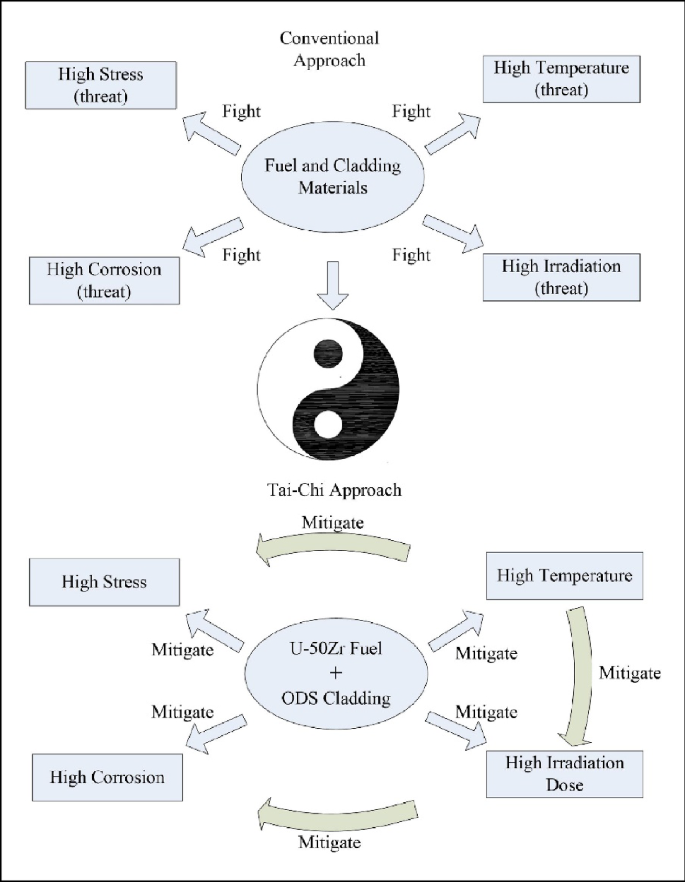
Proposed TWR concepts usually adopt metallic nuclear fuel designs due to their very high breeding ratio among various nuclear fuel forms. Metallic fuels also possess extraordinary inherent safety features that have been demonstrated in real reactor loss of flow accident (LOFA) and loss of heat sink accident (LOHSA). 11 , 12 In this article, we propose a novel metallic fuel concept based on the rationale of Chinese “Tai-Chi” Kungfu element, which essentially maneuvers unconventional reactor operations to mitigate performance challenges of fuels and materials faced by the TWR fuel design. In the following, the challenges to the fuels and cladding materials designs are outlined first. The disadvantages of a conventional approach to design TWR fuels are analyzed before the novel design concept is described in detail.
Challenges on fuels and cladding materials toward high burnups
High swelling, high gas release, and high fcmi.
Despite its obvious advantages on thermal conductivity, breeding ratio, and inherent safety, metallic fuel has some obvious disadvantages. On one hand, it is easy for metallic fuels to form phases between cladding and fuel slug with low solidus temperature; on the other hand, metallic fuels are subject to excessive fuel swelling caused by fission gas bubbles and voids under typical fast reactor conditions. Irradiation-induced swelling, and fission gas release are key limiting factors that restrict fuel performance of metallic fuels toward high burnup. To be specific, U-10Zr and U-Pu-10Zr fuels experience rapid swelling during the first several fractional percent FIMA (fissions per initial metal atom) up to 2% FIMA burnup until the fuel volumetric swelling strain reaches a threshold. At this threshold of fuel swelling strain (typically 30% volumetric strain), a large fraction of fission gas in the metallic fuel is vented to the gas plenum by a fission gas release mechanism related to formation and interconnection of open porosity. 13 Thus, once the fuel swelling threshold is reached, fission gas can only make a marginal contribution to the extra swelling strain in the mid fuel burnup range until open porosity becomes closed by accumulation of solid fission products. The prominent volumetric increase of metallic fuels needs to be accommodated in order to relieve fuel cladding mechanical interaction (FCMI). Fission gas, which either stays in the fuel matrix, causing significant swelling, or gets vented to the gas plenum, leading to high internal gas pressure, poses a major challenge to the fuel design. 14
Fuel cladding chemical interaction (FCCI) has been considered the most important life-limiting factor of metallic fuels at mid- to high burnups. The rapid fuel swelling at 1–2% burnup brings the fuel and the cladding into contact, and the interdiffusion of fuel and cladding constituents forms eutectic phases near the fuel-cladding interface. 15 For instance, U 6 Fe and UFe 2 can be formed by the interdiffusion of uranium and iron. 16 These eutectic phases can potentially lead to fuel melting during reactor transients.
A more important aspect of FCCI is related to the infiltration of lanthanides (mostly Nd and Ce) into the cladding that causes localized embrittlement of the cladding. This is a complicated process as the regions near the fuel-cladding interface are actually composed of several distinct FCCI layers. In addition to lanthanide precipitates along prior austenite grain boundaries, compounds composed of lanthanides and cladding components were also found in previous studies. Some of the compounds were determined to be (Fe,Cr) 17 Ln 2 or (Fe,Cr) 3 Ln, and the remaining are yet to be determined. The cladding regions penetrated by lanthanides have little mechanical strength and are termed “wastage zones” in previous FCCI studies. 16 , 17 It is currently believed that the lanthanides are transported into the cladding through a “liquid-like” diffusion mechanism. 16 The interconnecting pores in irradiated metallic fuels are filled (or at least partially filled) with liquid sodium from the initial sodium bond and volatile elements such as cesium from fission reactions. These liquid-filled pores offer accelerated diffusion paths for lanthanides. Although volatile fission products could not be avoided, elimination of liquid sodium (or other liquid metals) has the potential to significantly suppress such “liquid-like” diffusion processes and delay the onset of lanthanide attack near the inner surface of the cladding.
High fast neutron irradiation dose
Ferritic/martensitic steels such as HT-9 and 9Cr steels are being recognized as candidate materials for the metallic fuel-cladding in SFRs due to their high thermal conductivities, low expansion coefficients, and superior irradiation resistances to void swelling. 18 When materials are subject to the extreme conditions in a reactor, the irradiation-induced supersaturated point defects and clusters are inevitably affected by the coupling effect of stress and temperature, resulting in radiation damages and mechanical degradation of materials. The irradiation creep, which occurs under tensile stress lower than the yield stress, has been found to seriously affect the lifetime of materials, including fuel-cladding. This is also a major challenge for metallic fuels at high fuel burnup.
Long-term corrosion of cladding materials
Liquid metal (e.g., lead or lead–bismuth eutectic [LBE]) is used as a coolant for advanced fast reactors due to their excellent heat transfer properties, such as low melting point, high thermal conductivity, low viscosity, etc. However, liquid metal is naturally highly corrosive, especially at high temperatures. In the fast reactor environments, corrosion of the metallic fuel-cladding materials occurs primarily through the selective dissolution of alloy components into the liquid metal coolants, and the corrosion rate depends on the composition of the alloys and impurities of the liquid metal. 19 , 20 Moreover, the liquid metal could penetrate into the cladding materials along the grain boundaries and induce intergranular corrosion. 21 The composition and structural changes due to the selective dissolution and intergranular corrosion will lead to metallic cladding materials failure, especially under the high-temperature flowing lead or LBE conditions.
In view of the corrosion and degradation of metallic materials in lead or LBE environments, a widely used way of mitigating corrosion is to form a protective oxide scale on the surface of metallic materials by controlling the oxygen concentration that allows oxidation of the alloy but not oxidation of the liquid metal. For temperatures above 500°C, other measures such as coating or surface alloying need to be taken because the consumption of alloys due to oxidation could be rather fast at higher temperatures. Although these methods can mitigate materials corrosion, they are insufficient for protecting metallic cladding at high fuel burnup. It is found that the protection of alloys by forming an oxide layer has high requirements on oxygen control, and the oxide scale could fail due to the dissolution or thermal stress during the long-term exposure in liquid metal. Similarly, the disadvantage of material surface coating or surface alloying is that it is not self-repairing, and has the risk of cracking and peeling off due to thermal stress induced by different coefficients of thermal expansion compounded by the rather strong irradiation effects at high fuel burnups. Corrosion of cladding materials is another major challenge for the high fuel burnup conditions.
Conventional approach to the materials challenges
The conventional approach to face the fierce materials challenges is to utilize various design elements to minimize the damage caused by each of the previously mentioned threats and extend materials tolerance to these severe conditions as much as possible. For example, ODS steels have been proposed, which is expected to offer better performance characteristics under high-temperature, 22 , 23 high corrosive environments, 24 and high irradiation dose. 25 , 26 The underlying mechanism to support such performance improvement relies on the strengthening and enhanced defect sink strength by the dispersion oxide particles. 27 In addition, several metallic fuel designs were adapted to resolve the challenges posed by swelling and fission gas release under ultrahigh burnup: a low SD (smeared density), as low as 55%, was employed to accommodate the rapid swelling and avoid premature mechanical failure of the cladding; a gas venting mechanism to relieve the stress induced by the large amount of released fission gas; coating or liner on the cladding inner surface and/or targeted fuel alloy additions or adopting the annular metallic fuel design to mitigate FCCI. However, whether it's on the fuels or cladding materials, the conventional approach seems to only be able to further extend the failure limits by margins not satisfactory enough to meet the design requirements of TWRs.
Moreover, the efforts on the development of fuels and cladding materials more or less suffer from a scattered state: fuel performance analyses, analyses of irradiation effects and damage, corrosion analyses, and analyses of chemical processes were performed individually. A more integral approach has not yet been well established. For example, cladding materials such as HT-9 steels have been put to irradiation tests greater than 200 dpa, but the effects of a realistic stress state on the cladding tube and the synergistic effects were not considered. 28
The novel “Tai-Chi” approach
In this novel approach we call “Tai-Chi” approach, we present a fresh viewpoint with which we aim to gain at the seemingly unreachable 600 dpa irradiation dose limit on the cladding materials, higher than 40% FIMA burnup target on the fuels, 40–60 years of extensive corrosion time length on the cladding materials, at the same time. The reason behind the use of the word “Tai-Chi” is that the core philosophy of mitigating the fierce challenges by utilizing the possible benefits inherent to these challenges themselves is in good coherence with the Chinese “Tai-Chi” Kungfu element.
The schematic of moving from the conventional approach to the novel “Tai-Chi” approach is laid out in Figure 1 .

Schematic of the shift from a conventional approach to a novel “Tai-Chi” approach in solving the traveling wave reactor ultrahigh burnup metallic fuel problems. ODS, oxidation dispersion strengthened.
Detailed approach on “mitigating” the challenges
Use of annular u-50zr fuel, vented gas to mitigate the issue of high stress and fcci.
In order to reach a burnup as high as 40% FIMA or even higher, the FCMI issue is the most serious challenge as it becomes the biggest contributor to cladding failure after about 10–12% FIMA burnup for 72–75% SD U-10Zr and U–Pu-10Zr fuels. 29 Therefore, in the extensive irradiation length of the fuel under steady-state operation conditions, the fuel has to be swelling-resistant itself in the first place. FCCI is believed to be another major contributor to cladding failure, particularly under high temperatures. The fuel design has to inhibit the high-temperature eutectic formation scenario throughout its life cycle. The U-50Zr fuel possesses very peculiar and desirable characteristics viewing from these angles: it undergoes a spinodal decomposition transitioning from a hexagonal crystal structure phase to two separate cubic crystal structure phases, which are essentially swelling-resistant; it has a high-Zr content that diffusion processes are suppressed, which mitigate both the constituent redistribution issues and the FCCI issue of fission products corroding the inner surface of cladding materials; 30 at high enough temperature, the fuel evolves into a high plasticity γ-phase that can effectively creep toward the hollow center under an annular design upon fuel-cladding contact to reduce FCMI; the phase transition plus high temperature will promote extensive fission gas release, which will render the fuel material highly porous and hence FCMI ineffective.
An annular fuel design not only serves the purpose of allowing inward swelling at high-temperature scenarios and thereby reducing FCMI, but also acts as a way to alleviate FCCI issues. In the annular fuel design, the gap between the fuel and the cladding is significantly reduced compared to the solid (rod) design, allowing the use of inert helium gas as the heat transfer agent. The poor thermal conductivity of helium gas can be compensated by the small fuel-cladding gap. This eliminates the necessity of using liquid metal as the bonding material. Therefore, the annular fuel design can provide significant back-end benefits for fuel recycling. 31 , 32 Researchers have reported that in an annular U-10Zr fuel test, lanthanides did not accumulate at the fuel surface as they did in solid U-10Zr fuels. 33
Even for U-50Zr fuel, it is impossible to prevent fission gas from getting released to the gas plenum in large quantities. It needs to be stressed that fission gas release tends to be very strong in metallic fuels. Consequently, a vented fuel design was in place for the ultrahigh burnup metallic fuel design concept proposed by ANL researchers. Although fission gas release is considered less severe in low diffusion metallic fuel such as U-50Zr, it is ungrounded to think that fission gas release will still be suppressed at a burnup level as high as 40% FIMA. After all, any temperature surge event would fundamentally change the gas equation of state so as to promote gas release. As such, rather than attempting to contain the generated fission gas, the fuel design proposed in this work adopts the idea of vented fuel in the earlier ANL design.
In this design, fission gas release is in fact welcomed as any fission gas contained in the fuel will eventually form bubbles and cause fuel swelling to some extent. Thus, it becomes imperative to release nearly all gas generated in the fuel. This is obviously another challenge. In this work, the most important key design element is actually to purposefully introduce a high-temperature transient, though well controlled and safe so it could be viewed as a “normal” reactor operation. There is a common misunderstanding in metallic fuels, that is, its low melting temperature and hence the small temperature difference between its operating temperature and the solidus line is a huge disadvantage of the fuel. However, one needs to consider not only the magnitude of the temperature difference but also the magnitude of temperature rise per unit input power. The U-10Zr metallic fuel is fabulous in its ability to resist power and temperature surge scenarios. The LOFA and LOHSA experiments performed on the EBRII reactor completely astonished the entire world as a perfect showcase of the inherent safety feature of metallic fuels. 11 , 12 The more recent experiments by Kilopower has demonstrated the perfect load following abilities of yet another metallic fuel form, UMo. 34 The strong negative temperature feedback largely relaxes concerns with such fuel operating at high temperatures over a short period of time.
In fact, we purposefully introduce a high-temperature transient operation scenario, which is aimed at releasing all stored fission gas so as to prohibit strong swelling due to existing fission gas contained in the fuel matrix once the fuel is back in its lower temperature steady-state operation. Phase field simulations (the details of which are provided in the Supplementary Materials) showed that fission gas atoms and bubbles tend to accumulate on the phase boundaries between the two cubic phases, as depicted in Figure 2 , which is a location that is believed to foster gas release. When fuel temperature is raised above the phase-transition temperature of U-50Zr fuel (630°C, but this temperature tends to shift to a higher value when irradiation effects are present), the phase-change process will bring about significant driving force for gas atom diffusion. In addition, when the temperature reaches a higher temperature exceeding the phase transition point, fission gas will be driven to be released due to the high temperature. It is reasonable to expect that fission gas release will be near 100% once fuel temperature exceeds 850°C. This is consistent with the commonly observed fission gas release behaviors in fast reactor fuels such as those in UN, that gas release would be nearly full when temperature exceeds 50–55% of the fuel melting temperature. 35 In such a way, a cyclic operation procedure may be established that accumulates fission gas in the fuel matrix on phase boundaries during steady-state operation for the long-term, and then releases a large fraction of these gases during the high-temperature transients over a short-term operation. A schematic of cyclic fission gas release is provided in Figure 3 . Venting fission gas in this way can actually help gauge the real-time fuel temperature in this transient process through pressure sensors in the gas vent line in a fuel assembly. The readily available 3D printing technology renders design of complex geometry thin-walled pipelines feasible for such a gas collection and pressure measurement system. 36 Work is in progress to carry out an exact design of this gas collection system with pressure sensors and an algorithm to back out the temperature distribution in the fuel at real time with a good precision level.

(Left) The distribution of Zr-rich phase (red zones) and U-rich phase (blue zones) and (right) the distribution of fission gas atoms in U-50Zr in a spinodal decomposed state (~4% fissions per metal atom burnup).

Schematic of fission gas release (FGR) with cyclic high-temperature transient scenarios.
Finally, when the high-temperature transient operation is over, temperature of the fuel is gradually taken down to the steady-state operation temperature where a phase transition from the high-temperature γ-phase back to the lower temperature spinodal decomposed cubic phases takes place. The phase transitions from the lower steady-state temperature to the higher transient counterpart and then back to the original state will help sweep the accumulated irradiation defects from within the fuel matrix to the phase and grain boundaries. As fission products can lead to FCCI issues when they migrate to the fuel outer surface, the behaviors of these fission products under phase transitions and high-temperature operations need to be clarified in the future. The annular fuel is, in fact, specifically designed to keep a gap between the fuel slug and the cladding over steady-state long-term operation, so as to prevent FCCI by accumulation of lanthanide fission products at the outer surface of the fuel.
Utilizing irradiation-enhanced diffusion to mitigate the corrosion problem
Ferritic/martensitic steels such as HT-9 and 9Cr steels are being recognized as candidate materials for the metallic fuel-cladding in fast reactors. 37 It is known that ferritic/martensitic steels derive their corrosion resistance from the formation of compact oxide scale on the surface of materials by carefully controlling the oxygen content in the liquid metal. 38 It has been reported that the oxide layer has a duplex structure composed of a compact Fe–Cr spinel inner layer and a porous external magnetite layer in contact with the liquid metal. 39 According to the “available space model,” 40 on one hand, iron ions diffuse from the metal to the external interface leading to the growth of magnetite and formation of vacancies that could accumulate to form nanocavities at the metal/Fe–Cr spinel interface. On the other hand, the Fe–Cr spinel layer grows at the metal/oxide interface because oxygen diffuses easily inside the oxide scale through the nanocavities until the internal interface to generate Fe and Cr spinel. It is the outward diffusion rate of Fe rather than the inward diffusion rate of oxygen that controls the corrosion rate of ferritic/martensitic steels. 41 Thus, an effective method to reduce the corrosion rate of cladding materials is to reduce the diffusion rate of Fe through Fe–Cr spinel oxide.
An Ellingham diagram of Gibbs fee energy change versus temperature for the formation of metal oxides is shown in Figure 4 . Based on the thermodynamic calculations, it is seen that the formation Gibbs free energies of Cr, Mn, Al, and Si oxides is lower than that of Fe, indicating that the addition of Cr, Mn, Al, and Si contents in cladding materials is beneficial to enhance the oxide scale compactness and therefore can reduce the outward diffusion of Fe and improve its corrosion resistance in liquid metal environments. 42 However, due to the lower contents of Mn, Al, and Si in ferritic/martensitic steels (e.g., the Mn content is usually lower than 1 wt%), the oxide scales formed on their surface are Fe–Cr oxides. Thus, if we could find a method, without changing the composition of the ferritic/martensitic alloys, which can effectively enhance the diffusion rate of Mn and Cr and increase the concentration of these elements at the oxide layer, it will significantly improve the corrosion resistance of cladding materials in liquid metal and could be satisfactory enough to meet the design requirements of TWRs.

Ellingham diagram for metal oxides. 42
It has been reported that the composition and structure of oxides on materials are different after different surface treatment. Chen et al . 43 studied high-temperature oxidation characteristics of ultrafine ferrite—martensitic steel in air at 650°C and its corrosion behavior in liquid LBE. Results showed that a slight improvement in oxidation resistance was observed in an ultrafine-grained sample fabricated by 94% cold forge deformation. It is known that cold forge could enhance the high-angle grain boundaries as well as defects and dislocation concentrations, and accelerate the diffusion rate of Mn. 44 Therefore, a Mn-rich oxide (MnCr 2 O 4 and Mn 2 O 3 ) was formed in the ultrafine-grained ferritic/martensitic steels and the presence of Mn-rich oxide suppressed the corrosive attack of LBE and the outward diffusion of Fe. Similarly, a large amount of vacancies and interstitials can be produced when materials are subjected to irradiation, especially upon high-dose fast neutron irradiation. The high defect concentrations could accelerate the diffusion and improve the oxidation behavior of materials. Yao et al . 45 reported that ion irradiation not only resulted in a significant increase in thickness of surface oxides, but also remarkably modified the microstructure of oxides in comparison with the corroded samples without irradiation. The effect of irradiation on the corrosion process was believed to be mostly related to the radiation-enhanced diffusion. We found similar results in our recent studies. Figure 5 presents the oxide scale formed on the surface of MX-ODS steel without and with Fe irradiation at 550°C (sample without irradiation was an area blocked from irradiation but experienced the same 550°C conditions). As shown in Figure 5 , a compact oxide film with an average thickness of about 40 nm was formed on the surface of ODS steel after Fe irradiation, which is much thicker than that without irradiation (the oxide film without irradiation was around 5 nm according to Figure 5 ). In addition, the oxides are rich in Mn and Cr according to the EDS maps. Combined with XRD and TEM, it was revealed that the oxide film formed on the MX-ODS steel was (Cr, Mn) 2 O 3 after irradiation. The irradiation-induced supersaturated point defects and clusters are inevitable in advanced fast neutron reactors or TWR. Based on the previously discussed results, the extreme radiation environments in reactors can possibly provide a potential way to accelerate the diffusion of elements and improve the thickness and structure of oxides formed on the candidate cladding materials and replenish irradiation-induced defects, such as nanovoids and nanoscale cracks, by supply of additional matrix atoms, before the defects further grow to become extensive. In fact, recent research has reported that proton irradiation decelerates intergranular corrosion of Ni–Cr alloys in molten fluoride salt at 650°C. Researchers demonstrated this by showing that the depth of intergranular voids resulting from Cr leaching into the salt is reduced by proton irradiation. Irradiation-induced interstitial defects enhanced diffusion, more rapidly replenishing corrosion-induced vacancies with alloy constituents, thus playing a crucial role in decelerating corrosion. 46 Thus, the corrosion resistance of the metallic cladding in liquid metal environments can be improved.

Cross-sectional image and corresponding energy-dispersive spectroscopy maps of MX-ODS steel without (left) and with (right) Fe irradiation at 550°C.
It should be pointed out that although irradiation could improve the oxide structure and thickness of oxide scale, the irradiation-accelerated corrosion would be a challenge as well for the development of metallic cladding materials. It is known that the solubility of Mn in pure lead is much higher than that of Fe and Cr, that could affect the long-term corrosion resistance of Mn-rich oxide in liquid metal. Thus, in the future, more irradiation-oxidation and irradiation-corrosion experiments will be necessary to confirm the feasibility of utilizing irradiation-enhanced diffusion to treat the corrosion problem of metallic cladding in advanced fast neutron reactors or TWRs.
Use of controlled high-temperature transient to anneal cladding materials in-pile
It has been long believed that there will be so many problems, which the cladding materials need to face in order to survive 600 dpa or higher fast neutron irradiation dose. The issue of irradiation-induced breakaway void swelling has to be solved in the first place. The best performing swelling-resistant material that has been evaluated thoroughly is the ferritic/martensitic HT-9 steel, which has the potential to perform well up to about 200 dpa. 47 In view of the vast gap between the do-able and the desirable, we hereby propose an unorthodox approach of “mitigating” the swelling issue by utilizing the benefits of the earlier proposed high-temperature transient (i.e., in-pile heat treatment [or thermal annealing]).
Swelling is known to have an incubation period when voids stay at small sizes after nucleation and when vacancy supersaturation has not been fully established. 48 This incubation period could extend from 30 to 40 dpa in austenitic steels to more than 80 dpa in F/M steels such as HT-9. 18 It is believed that such incubation period could be even longer for ODS steels. A large amount of irradiation tests have demonstrated that swelling has a bell shape dependence on temperature and at high enough temperatures irradiation swelling will remain low due to activation of diffusion of defect clusters of opposite natures (i.e., interstitial and vacancy), which then leads to annealing of irradiation defects. 49 In our scenario, the situation is slightly different as it acts more like an out-of-pile annealing when the defects are generated by long-term irradiation effects at lower temperatures (i.e., steady-state operation) while they are annealed at a higher temperature for a comparatively much shorter time length (6–8 h), as schematically illustrated in Figure 3 . However, as long as the vacancy supersaturation has not been established, raising the cladding temperature will result in annealing effects. The reason that in-pile annealing has not been done conventionally is that, on one hand, the cladding may undergo plastic deformation at such high temperatures; on the other hand, even if the cladding remains elastic, the creep would become so high that the cladding could breech in hours, if not minutes. In such a case, it is not that there cannot be a high stress level on the cladding materials, it is rather that there cannot be nearly any stress to activate significant thermal creep. As we suggested earlier, FCMI could be effectively mitigated once the fuel operates at a high enough temperature in its γ-phase. This has been, in fact, demonstrated in the AFC-3 rodlet tests when abnormal high temperature was induced due to manufacturing problems in the fuel-cladding interface. 31 But then, even if FCMI can be maintained at a low level, it does not necessarily mean it is low enough to avoid the thermal creep scenario.
Therefore, in this design, we introduce another key element: a force balance mechanism on the cladding material under the high-temperature transient operation scenario. We begin by introducing a pressure in the primary loop or the pressure vessel for the pool design and introduce an internal pressure in the fuel pin with prefilled He. The internal pressure is purposefully set slightly lower than the external one, and the small pressure difference and the net external pressure are not going to cause issues under the steady-state operation as the temperature of the cladding does not allow effective creep. In addition, the strength of MX-ODS or 14YWT ODS steels at the steady-state operation temperature regime is robust from a design perspective. 50 , 51 The U-50Zr fuel is designed to be annular in shape leaving a gap between the fuel and the clad to accommodate fuel outward swelling during the steady-state operation. 52 The design of the central hole of the fuel is a little intricate as it serves two main purposes: (1) due to the axial temperature difference between the bottom part and top part of the fuel pin, the top higher temperature part will see phase transition even at the low temperature steady-state operation, the central hole then leaves space for the high-temperature γ-phase to creep inward due to the stiff nature of the outer spinodal decomposed cubic phase nanostructured U-50Zr fuel; (2) one would also want the fuel central hole to close at very high burnup so the fuel only experiences a gas pressure from the gap to press it so as to further inhibit strong swelling. On raising the cladding temperature, the external pressure on the cladding will increase according to the ideal gas law. As the coefficients of thermal expansion of the clad are higher than that of the fuel, the gap between the fuel and clad will enlarge. 18 , 53 The resulting fuel temperature rise due to gap enlargement and temperature rise of the coolant will produce one major effect: large amounts of fission gas will be released to the plenum due to the temperature rise. An internal pressure control mechanism is proposed here, which relies on a pressure control device at the top fuel cap designed by researchers from ANL. 54 A diving bell type device is put in place so that only when fuel internal pressure exceeds a certain level does it open to vent the gas. Once enough gases are vented to the gas collection system, the pressure reduces back to the pressure control level set by the mass of the diving bell such that the internal pressure in the plenum can be effectively maintained at a constant. At high temperatures, the fuel, after releasing fission gas, will be a porous material, and its high creep rate will relieve FCMI even if the fuel contacts the clad. And the internal gas pressure is effectively operating on the internal surface of the cladding material, so a very intricate force balance may be obtained if the internal control pressure is set to be exactly the same as the expected pressure in the coolant channel at the designated cladding heat treatment temperature. A schematic of such a design in shown in Figure 6 . Under such a force balance, the strain increment of the MX-ODS or 14YWT ODS steels can be kept at a low level, if not none, such that cladding failure due to significant thermal creep is avoided. The irradiation effects in the MX-ODS or 14YWT ODS steel cladding materials are left to annealing at the high temperature for the transient operation for 6–8 h.

Relationship between gas pressure in plenum and pressure in the coolant channel over multiple cycles of steady-state and transient operations (Box colors: blue: initial pressure level; green: low pressure level; red: high pressure level; arrow colors: blue: initial pressure level; brown: pressure at elevated levels).
The detailed cycle-by-cycle operation and the relationship between gas pressure in plenum and pressure in the coolant channel is illustrated in Figure 6 . It is further elaborated that if the pressure by the diving bell can be controlled by any means, a more straightforward mechanical balancing scheme may be achieved by setting the plenum inner pressure to the outer pressure in the primary loop.
It needs to be further noted that the axial temperature gradient on the cladding requires us to consider both the higher temperature top part and the lower temperature bottom part of the cladding at these cyclic operation cycles. In order to avoid significant axial stress gradient, the reactor is proposed to run at zero power during the high-temperature annealing operation generating only decay heat. The heat exchanger interfacing the primary and secondary circuits will be operating at a low heat sink rate such that temperature of the primary coolant will rise slowly and flatten off at a designated temperature for annealing of cladding materials.
Moreover, when a fast reactor operates to very high fuel burnup levels, large amounts of helium will be produced forming helium bubbles. Formation of large helium bubbles tends to foster swelling and embrittlement of cladding. However, it has been demonstrated that in high-performance ODS steels such as 14YWT, helium bubbles remained small and dispersed after high-temperature annealing at 900°C in specimens pre-implanted with about 12,000 appm peak helium concentration, proving that helium bubble growth can be well suppressed in this ODS steel even at such high temperature. 55 As such, thermal annealing at temperatures not higher than 800°C for 6–8 h in our design will very probably not cause significant helium bubble growth nor the resulting high swelling.
Finally, it needs to be stressed that other aspects such as neutronics and thermohydraulics of this fuel design are out of the scope of this work and therefore their discussions are not included in this article. U-50Zr, due to the low uranium loading, may have issues in sustaining the traveling wave so a special core design or a mixed use of high-Zr and low-Zr fuels may be necessary.
In this article, we carried out a fuel element design at a conceptual level to serve the purpose of reaching ultrahigh fuel burnup for a metallic fuel form. The core disadvantages of the conventional approach were laid out where the raised challenges are believed to be so fundamental and profound that such conventional approach is rendered ineffective. Based on the rationale of the Chinese “Tai-Chi” Kungfu element, a new and unorthodox approach was proposed to utilize the possible benefits of high temperature to manifest periodic fission gas release to relieve the FCMI challenge and, at the same time, use the annealing benefits of such high-temperature operation to treat irradiation effects on the cladding materials. In addition, a phenomenon that irradiation boosts transport of Mn and Cr elements to the cladding surface to form a dense and protective thin oxide as a self-repairing mechanism was discovered and is believed to be able to help mitigate the long-term corrosion challenge by liquid lead. This innovative conceptual design shifts the conventional strategy to maximize materials irradiation tolerance from a sole materials perspective to a new strategy that maneuvers thermohydraulic operations to elongate materials life under the extreme conditions in a TWR-type fast reactor.
Data availability
Data of this work will be made available upon reasonable request.
B. Gates, How to Avoid a Climate Disaster: The Solutions We Have and the Breakthroughs We Need , Chinese edn., ed. by Z. Chen (Citic Press Corporation, Beijing, 2021), pp. 55–56
Google Scholar
M.Y. Yan, H. Sekimoto, Ann. Nucl. Energy 35 , 18 (2008)
Article CAS Google Scholar
K.D. Weaver, C. Ahlfeld, “Extending the Nuclear Fuel Cycle with Traveling-Wave Reactors,” in Proceedings of the Global 2009 Congress - The Nuclear Fuel Cycle: Sustainable Options and Industrial Perspectives (Paris, September 6–11, 2009), pp. 92–94
D. Zhang, X.-N. Chen, M. Flad, A. Rineiski, W. Maschek, Energy Convers. Manage. 72 , 12 (2013)
A.G. Osborne, M.R. Deinert, Ann. Nucl. Energy 62 , 269 (2013)
M.K. Saadi, A. Abbaspour, A. Pazirandeh, Ann. Nucl. Energy 50 , 44(2012)
Article Google Scholar
R. Petroski, B. Forget, C. Forsberg, Nucl. Eng. Des. 250 , 364 (2012)
R. Petroski, B. Forget, C. Forsberg, Ann. Nucl. Energy 55 , 151 (2013)
S. Fomin, Yu. Mel’nik, V. Pilipenko, N.N. Shul’ga, Ann. Nucl. Energy 32 (13), 1435 (2005)
M.Y. Yan, Study on Small Long Life CANDLE Fast Reactor, Sekimoto Laboratory Research Laboratory for Nuclear Reactor, Tokyo Institute of Technology, ci. nii.ac.jp, 2007
P.H. Royl, J.E. Cahalan, G. Friedel, G. Kussmaul, J. Moreau, M. Perks, R.A. Wigeland, Nucl. Technol. 97 (2), 198 (1992)
G.H. Golden, H.P. Planchon, J.I. Sackett, R.M. Singer, Nucl. Eng. Des. 101 (1), 3 (1987)
J. Rest, J. Nucl. Mater. 207 , 192 (1993)
T. Ogata, “Metal Fuel,” in Comprehensive Nuclear Materials, Volume 3: Advanced Fuels/Fuel Cladding/Nuclear Fuel Performance Modeling and Simulation (Elsevier, Amsterdam, 2012), chap. 3.01, p. 1
D.D. Keiser, J. Nucl. Mater. 514 , 393 (2019)
C. Matthews, C. Unal, J. Galloway, D.D. Keiser, S.L. Hayes, Nucl. Technol. 198 (3), 231 (2017)
Y. Miao, A. Oaks, K. Mo, M. Billone, C. Matthews, A.X. Zabriskie, S. Novascone, A.M. Yacout, Nucl. Eng. Des. 385 , 111531 (2021)
Y. Chen, Nucl. Eng. Technol. 45 (3), 311 (2013)
J. Zhang, Corros. Sci. 51 (6), 1207 (2009)
R.G. Ballinger, J. Lim, Nucl. Technol. 147 (3), 418 (2004)
M. Kondo, M. Takahashi, T. Suzuki, K. Ishikawa, K. Hata, S. Qiu, H. Sekimoto, J. Nucl. Mater. 343 , 349 (2005)
S. Ukai, M. Fujiwara, J. Nucl. Mater. 307 , 749 (2002)
S.J. Zinkle, J.L. Boutard, D.T. Hoelzer, A. Kimura, R. Lindau, G.R. Odette, H. Tanigawa, Nucl. Fusion 57 (9), 092005 (2017)
O. Yeliseyeva, V. Tsisar, Z. Zhou, J. Nucl. Mater. 442 , 434 (2013)
M.B. Toloczko, F.A. Garner, V.N. Voyevodin, V.V. Bryk, O.V. Borodin, V.V. Mel'nychenko, A.S. Kalchenko, J. Nucl. Mater. 453 , 323 (2014)
G.R. Odette, D.T. Hoelzer, JOM 62 (9), 84 (2010)
G.R. Odette, JOM 66 (12), 2427 (2014)
J.J. Kai, G.L. Kulcinski, J. Nucl. Mater. 175 (3), 227 (1990)
P. Mohanakrishnan, O.P. Singh, K. Umasankari, Physics of Nuclear Reactors (Academic Press, New York, 2021), pp. 701
T. Yao, A. Sen, A. Wagner, F. Teng, M. Bachhav, A. El-Azab, D. Murray, J. Gan, D. Hurley, J. Wharry, M.T. Benson, L. He, Materialia 16 (31), 101092 (2021)
J.M. Harp, H.J.M. Chichester, L. Capriotti, J. Nucl. Mater. 509 , 377 (2018)
T. Yao, L. Capriotti, J.M. Harp, X. Liu, Y. Wang, F. Teng, D.J. Murray, A.J. Winston, J. Gan, M.T. Benson, L. He, J. Nucl. Mater. 542 , 152536 (2020)
X. Liu, L. Capriotti, T. Yao, J.M. Harp, M.T. Benson, Y. Wang, F. Teng, L. He, J. Nucl. Mater. 544 , 152588 (2021)
D.I. Poston, M.A. Gibson, R.G. Sanchez, P.R. McClure, Nucl. Technol. 206 , 89 (2020)
J. Wallenius, J. Nucl. Mater. 558 , 153402 (2022)
A. Hehr, J. Wenning, K. Terrani, S.S. Babu, M. Norfolk, JOM 69 (3), 485 (2017)
X. Gong, M.P. Short, T. Auger, E. Charalampopoulou, K. Lambrinou, Prog. Mater Sci. 126 , 100920 (2022)
I.V. Gorynin, G.P. Karzov, V.G. Markov, V.A. Yakovlev, Met. Sci. Heat Treat. 41 , 384 (1999)
J. Liu, Z.Z. Jiang, S.J. Tian, Q.Y. Huang, Y.J. Liu, J. Nucl. Mater. 468 , 299 (2016)
L. Martinelli, F. Balbaud-Célérier, A. Terlain, S. Delpech, G. Santarini, J. Favergeon, G. Moulin, M. Tabarant, G. Picard, Corros. Sci. 50 (9), 2523 (2008)
L. Martinelli, F. Balbaud-Célérier, A. Terlain, S. Delpech, G. Santarini, J. Favergeon, G. Moulin, M. Tabarant, G. Picard, Corros. Sci. 50 (9), 2537 (2008)
M. Hasegawa, “Ellingham Diagram,” in Treatise on Process Metallurgy, Volume 1: Process Fundamentals (Elsevier, Amsterdam, 2014), chap. 3.3, pp. 507–516
Book Google Scholar
S. Chen, L. Rong, Acta Metall. Sin. 57 (8), 989 (2021)
CAS Google Scholar
S. Chen, L. Rong, Oxid. Met. 89 (3-4), 415 (2018)
C. Yao, H. Zhang, H. Chang, Y. Sheng, T. Shen, Y. Zhu, L. Pang, M. Cui, K. Wei, Y. Xu, D. Wang, C. Liu, Z. Ma, L. Zhao, W. Yan, T. Peng, J. Li, C. Qin, Z. Wang, Corros. Sci. 195 , 109953 (2022)
W. Zhou, Y. Yang, G. Zheng, K.B. Woller, P.W. Stahle, A.M. Minor, M.P. Short, Nat. Commun. 11 , 3430 (2020)
J. Henry, S.A. Maloy, “Irradiation-Resistant Ferritic and Martensitic Steels as Core Materials for Generation IV Nuclear Reactors,” in Structural Materials for Generation IV Nuclear Reactors, ed. by P. Yvon (Elsevier, Amsterdam, 2017), chap. 9, pp. 329–355
G.S. Was, D. Petti, S. Ukai, S. Zinkle, J. Nucl. Mater. 527 , 151837 (2019)
J.F. Bates, R.W. Powell, J. Nucl. Mater. 102 , 200 (1981)
G. Wang, Y. Li, J. Zhang, F. Bao, Y. Wei, Q. Shi, X. Shi, Y. Shan, K. Yang, Fusion Eng. Des. 160 , 111824 (2020)
D.T. Hoelzer, J. Bentley, M.A. Sokolov, M.K. Miller, G.R. Odette, M.J. Alinger, J. Nucl. Mater. 367–370 , 166 (2007)
A.E. Wright, S.L. Hayes, T.H. Bauer, H.J. Chichester, G.L. Hofman, J.R. Kennedy, T.K. Kim, Y.S. Kim, R.D. Mariani, W.D. Pointer, A.M. Yacout, D. Yun, “Development of Advanced Ultra-High Burnup SFR Metallic Fuel Concept – Project Overview,” in Proceedings of Nuclear Fuels and Structural Materials for the Next Generation Nuclear Reactors (NFSM 2012) , Embedded Topical Meeting of 2012 American Nuclear Society Annual Meeting (Chicago, June 24–28, 2012)
A.C. Bagchi, G.J. Prasad, K.B. Khan, R.P. Singh, Trans. Indian Inst. Met. 67 (1), 123 (2014)
A.E. Wright, T.K. Kim, D. Yun, W.D. Pointer, G. Bozzolo, A.M. Yacout, Y.S. Kim, T.H. Bauer, K. Grimm, A.R. Kraus, Development of Advanced Ultra-high Burn-up SFR Metallic Fuel Concept – FY2011 Status Report (ANL-FCT-329, Argonne National Laboratory, September 2011)
Y.-R. Lin, W.-Y. Chen, L. Tan, D.T. Hoelzer, Z. Yan, C.-Y. Hsieh, C.-W. Huang, Acta Mater. 217 , 117165 (2021)
Download references
Acknowledgments
This work was supported by the National Natural Science Foundation of China, Grant No. 11675126 And the State Key Research and Development Program of China, Grant No. 2020YFB1902100.
Author information
Authors and affiliations.
School of Nuclear Science and Technology, Xi’an Jiaotong University, Xi’an, China
Linna Feng, Yuwen Xu, Jie Qiu, Chunyang Wen, Zhengyu Qian, Wenbo Liu, Zhaohao Wang, Shilun Zheng, Shaoqiang Guo, Tan Shi, Chenyang Lu, Junli Gou, Liangxing Li, Jianqiang Shan & Di Yun
Nuclear Power Institute of China, Chengdu, China
Laboratory for Advanced Nuclear Energy Theory and Applications, Zhejiang Institute of Modern Physics, Department of Physics, Zhejiang University, Hangzhou, China
CAS Key Laboratory of Nuclear Materials and Safety Assessment, Institute of Metal Research, Chinese Academy of Sciences, Shenyang, China
Wei Yan & Yanfen Li
Shi-Changxu Innovation Center for Advanced Materials, Institute of Metal Research, Chinese Academy of Sciences, Shenyang, China
Department of Nuclear, Plasma and Radiological Engineering, University of Illinois at Urbana-Champaign, Champaign, USA
James F. Stubbins
Institute of Modern Physics, Chinese Academy of Sciences, Lanzhou, China
University of Chinese Academy of Sciences, Beijing, China
School of Nuclear Science and Technology, Lanzhou University, Lanzhou, China
You can also search for this author in PubMed Google Scholar
Corresponding author
Correspondence to Di Yun .
Ethics declarations
Conflict of interest.
The authors declare that they have no known competing financial interests or personal relationships that could have appeared to influence the work reported in this paper.
Supplementary Information
Below is the link to the electronic supplementary material.
Supplementary file1 (DOCX 94 KB)
Rights and permissions.
Open access This article is licensed under a Creative Commons Attribution 4.0 International License, which permits use, sharing, adaptation, distribution and reproduction in any medium or format, as long as you give appropriate credit to the original author(s) and the source, provide a link to the Creative Commons license, and indicate if changes were made. The images or other third party material in this article are included in the article's Creative Commons license, unless indicated otherwise in a credit line to the material. If material is not included in the article's Creative Commons license and your intended use is not permitted by statutory regulation or exceeds the permitted use, you will need to obtain permission directly from the copyright holder. To view a copy of this license, visit http://creativecommons.org/licenses/by/4.0/ .
Reprints and permissions
About this article
Feng, L., Xu, Y., Qiu, J. et al. A novel approach on designing ultrahigh burnup metallic TWR fuels: Upsetting the current technological limits. MRS Bulletin 47 , 1092–1102 (2022). https://doi.org/10.1557/s43577-022-00420-4
Download citation
Accepted : 09 September 2022
Published : 03 November 2022
Issue Date : November 2022
DOI : https://doi.org/10.1557/s43577-022-00420-4
Share this article
Anyone you share the following link with will be able to read this content:
Sorry, a shareable link is not currently available for this article.
Provided by the Springer Nature SharedIt content-sharing initiative
- Zero carbon
- Traveling wave reactor
- Nuclear fuels
- Irradiation effects
- High burnup
- Find a journal
- Publish with us
- Track your research
Institute for Energy and Environmental Research For a safer, healthier environment and the democratization of science
- Our Commitment
- Staff and Board
- Publications
- Newsletters
- Audio/Video
- Subject Index
- Archives (by date)
- Links to Other Sites
- Carbon-Free, Nuclear-Free
- The Renewable Maryland Project
- Healthy from the Start
- Disarmament and Nonproliferation
You are here: Home » Energy Issues » Traveling Wave Reactors: Sodium-cooled Gold at the End of a Nuclear Rainbow?
Traveling Wave Reactors: Sodium-cooled Gold at the End of a Nuclear Rainbow?
Bill gates on the wrong path with traveling wave reactors: despite $100 billion invested globally, sodium-cooled reactors plagued by leaks, accidents, and low reliability, report: twrs will likely be economically obsolete before they are commercialized.
| Download the full report |
WASHINGTON, D.C. – September 4, 2013 – Bill Gates’s heart is in the right place on climate: we do need to get to a very low carbon emissions energy system. But, when it comes to the traveling wave reactor, his money is not.
A new report from the nonprofit Institute for Energy and Environmental Research (IEER) think tank finds that the “traveling wave reactor” (TWR) concept championed by TerraPower, in which Bill Gates, of Microsoft fame, is a key investor, is likely to be a commercial failure. $100 billion already has been invested by over half a dozen countries over more than six decades in an unsuccessful commercialization effort. There has been essentially no demonstrable learning curve: the most recent sodium-cooled demonstration reactors in France and Japan have among the worst reliability records.
The “traveling wave reactor,” first conceived in 1958, has been intensively investigated only since about 2006. It is a sodium-cooled “fast” reactor design in which neutrons are not slowed down and the heat created by fission is carried away by liquid sodium, which is used to boil water. In turn, the steam is used to drive a turbine-generator set to generate electricity. A TWR has never been built. However, the TWR is a type of the sodium-cooled fast reactors that have been pursued with little success over several decades in several countries.
Titled “Traveling Wave Reactor: Sodium-cooled Gold at the End of a Nuclear Rainbow?,” the report concludes:
- The sodium-cooled reactor experience does not bode well for TWRs. “Sodium-cooled fast reactors have a checkered history. Some have operated well, while others have done poorly. The most recent commercial demonstration reactors belong in the latter category. The French demonstration reactor, Superphénix, operated at an average capacity factor of less than 7 percent over 11 years before being shut in 1996….The Japanese Monju reactor, commissioned in 1994, and connected to the grid in 1995, had a sodium leak and fire in 1995. It was closed until May 2010, when it was restarted for testing, but suffered another accident in August 2010. It has not been restarted since….”
- Power produced by TWRs would not be affordable or competitive. “Even apart from the poor reliability in many cases, sodium-cooled breeder reactor capital costs have been very variable and have not decreased over time. Fermi I, built in the 1960s, cost about $4,000 per kilowatt, while the Fast Flux Test Facility, operational in 1980, cost over $10,000 per kilowatt. Superphénix cost, commissioned in 1986, about $4,800 per kilowatt, but Monju, commissioned nearly a decade later, cost over $20,000 per kilowatt [all in 1996 dollars]. Proponents of sodium-cooled reactors, including traveling wave reactors, tend not to focus on how they plan to overcome the problematic parts of the sodium-cooled design history, centered in large part on sodium-related problems, but rather tend to focus on the vast available raw material to produce a large amount of power for the indefinite future. Overall, it is expected that costs of sodium-cooled breeders will be significantly higher than current reactors, despite the fact that about $100 billion have been spent worldwide (2007 dollars) on the attempt to commercialize sodium-cooled breeder reactors, so far without success.”
Arjun Makhijani, Ph.D., nuclear engineer and president, Institute for Energy and Environmental Research, and author of the TWR report, said:
“By focusing on the uranium resource issue, which is an economic non-problem for the foreseeable future, TWR proponents have lost sight of the practical problems that have prevented commercialization of sodium-cooled breeders despite immense effort and expense. Contrary to the claims of proponents, supplying most of the world’s electricity with TWRs would create significant proliferation risks, with or without reprocessing, were they to be used as a mainstay of global power generation. Moreover, given the reactor development that remains, it is highly unlikely that such reactors could help significantly alleviate the problem of fossil fuel generation in the next few decades, when it must be solved. TWRs are likely to be economically obsolete before there are commercialized.”
Dr. Makhijani, who is principal author of the first ever study of energy efficiency potential of the U.S. economy (1971), said he will send Mr. Gates his book, Carbon-Free and Nuclear-Free: A Roadmap for U.S. Energy Policy , and invite him to debate the path to a low carbon-emissions economy.
Report reviewer M.V. Ramana, Ph.D., Nuclear Futures Laboratory and Program on Science and Global Security, Woodrow Wilson School of Public and International Affairs, Princeton University, said:
“Sodium cooled fast neutron reactors have been pursued by several countries around the world. The lesson from the many decades of such pursuit has been that these reactors are expensive, are prone to operational problems and sodium leaks, and are susceptible to severe accidents under some circumstances. There is no evidence that the Traveling Wave Reactor will overcome any of these. It is not convincing even on paper.”
Other Key Findings
- Promised delivery dates for TWRs are wildly unrealistic. “TWR proponents aim to have a demonstration reactor operating by 2022 and the first commercial reactor by the late 2020s. This is an impossible schedule, at least for the United States. The TWR design, like other sodium-cooled reactors, is so different from presently licensed reactors that the Nuclear Regulatory Commission will have to write regulations specifically tailored for them. For instance, accident mechanisms in sodium-cooled breeders are different than in light water reactors. It will take years for the Nuclear Regulatory Commission to staff up and acquire the necessary data and expertise to write the rules and do the safety and risk evaluations. As a result, certification and licensing of a demonstration reactor design is likely to take much longer than proponents have allowed for so far. Perhaps that is why TerraPower is reportedly exploring agreements with China and India even though China has little experience with sodium-cooled breeder reactors and India’s record so far hardly inspires confidence, having been plagued by leaks and accidents.”
- Even if reducing the cost of uranium were possible with TWRs, it would not make nuclear power cheaper. “The main argument that has been made for TWRs is that they can greatly expand the use of the uranium resource without reprocessing. But a paucity of uranium resources is not holding back nuclear power – it is the capital cost of the reactors. Reducing the cost of uranium resources significantly will do almost nothing to alleviate this problem, since the cost of mined uranium in existing power plants is roughly two percent of the overall cost of nuclear power.”
- TWRs may be prone to radioactive leaks and core meltdowns. “… leaks have been a common problem in sodium-cooled breeder programs, including in France, the UK, India, Russia, and Japan. Core meltdown accidents can also occur: two of the U.S. sodium-cooled breeders have had partial core meltdowns. Sodium-cooled reactors have some safety advantages relative to present-day light water reactors, such as operation at low pressure, in contrast to light water reactors. But they also have safety disadvantages, including the potential for the reactor to continue to sustain a chain reaction in the event of coolant loss.”
See the full report at http://www.ieer.org .
The nonprofit Institute for Energy and Environmental Research provides interested parties with understandable and accurate scientific and technical information on energy and environmental issues. IEER’s aim is to bring scientific excellence to public policy issues in order to promote the democratization of science and a safer, healthier environment.
Media Contact : Ailis Aaron Wolf, (703) 276-3265 or [email protected]
Subject: Energy Issues , Nuclear Power , Press Releases and Briefings , Reprocessing , and Technical Reports . Posted on September, 2013. Last modified September, 2013. Download this page as a PDF
Download this page as a PDF
Related content:
- Renewable Minnesota: A technical and economic analysis of a 100% renewable-energy based electricity system for Minnesota
- Securing the Energy Future of the United States
Stay up to date with IEER
Institute for Energy and Environmental Research, © 2024
Back to Top • Home • Terms of Use
Engineering
Paper Video Conference Expert
Subscribe Submit
2016, Volume 2, Issue 1
Related Research
Back to Top
Engineering >> 2016, Volume 2, Issue 1 doi: 10.1016/J.ENG.2016.01.024
Research Nuclear Power
The Traveling Wave Reactor: Design and Development
TerraPower LLC, Bellevue, WA 98005, USA
Next Previous
The traveling wave reactor (TWR) is a once-through reactor that uses in situ breeding to greatly reduce the need for enrichment and reprocessing. Breeding converts incoming subcritical reload fuel into new critical fuel, allowing a breed-burn wave to propagate. The concept works on the basis that breed-burn waves and the fuel move relative to one another. Thus either the fuel or the waves may move relative to the stationary observer. The most practical embodiments of the TWR involve moving the fuel while keeping the nuclear reactions in one place−sometimes referred to as the standing wave reactor (SWR). TWRs can operate with uranium reload fuels including totally depleted uranium, natural uranium, and low-enriched fuel (e.g., 5.5% 235 U and below), which ordinarily would not be critical in a fast spectrum. Spent light water reactor (LWR) fuel may also serve as TWR reload fuel. In each of these cases, very efficient fuel usage and significant reduction of waste volumes are achieved without the need for reprocessing. The ultimate advantages of the TWR are realized when the reload fuel is depleted uranium, where after the startup period, no enrichment facilities are needed to sustain the first reactor and a chain of successor reactors. TerraPower’s conceptual and engineering design and associated technology development activities have been underway since late 2006, with over 50 institutions working in a highly coordinated effort to place the first unit in operation by 2026. This paper summarizes the TWR technology: its development program, its progress, and an analysis of its social and economic benefits.
Nuclear energy ; Electricity generation ; Advanced reactor ; Traveling wave reactor ; Sustainability

[ 1 ] Asafu-Adjaya J, Blomqvist L, Brand S, Brook B, DeFries R, Ellis E, An ecomodernist manifesto [Internet]. 2015[cited 2015Oct28]. Available from: http://www.ecomodernism.org/.
[ 2 ] Hejzlar P, Petroski R, Cheatham J, Touran N, Cohen M, Truong B, TerraPower, LLC traveling wave reactor development program overview. Nucl Eng Technol 2013; 45(6): 731−44. link1
[ 3 ] Chen SK, Petroski R, Todreas NE. Numerical implementation of the Cheng and Todreas correlation for wire wrapped bundle friction factors-desirable improvements in the transition flow region. Nucl Eng Des 2013; 263: 406−10. link1
[ 4 ] Mikityuk K. Heat transfer to liquid metal: review of data and correlations for tube bundles. Nucl Eng Des 2009; 239(4): 680−7. link1
[ 5 ] Engel FC, Minushkin B, Atkins RJ, Markley RA. Characterization of heat transfer and temperature distributions in an electrically heated model of an LMFBR blanket assembly. Nucl Eng Des 1980; 62(1−3): 335−47. link1
[ 6 ] Miller SJ, Latta R. Fuel performance modeling of traveling wave reactor fuel elements [poster session]. In: Materials Modeling and Simulation for Nuclear Fuels 2013 Workshop; 2013Oct14−16; Chicago, IL, USA; 2013.
[ 7 ] Cohen M, Werner M, Johns C. Mechanical model of a TerraPower, traveling wave reactor fuel assembly duct. In: 22nd International Conference on Structural Mechanics in Reactor Technology; 2013Aug18−23; San Francisco, CA, USA. Red Hook: Curran Associates, Inc.; 2014.
[ 8 ] Bates E, Truong B, Huddar L. Phase II of the EBR-II SHRT-45R benchmark study−TerraPower’s SAS4A/SASSYS-1 results. In: Proceedings of 2016 Advances in Reactor Physics−Linking Research, Industry, and Education (PHYSOR 2016); 2016May1−5; Sun Valley, ID, USA; Forthcoming 2016.
[ 9 ] Pahl R, Lahm CE, Hayes SL. Performance of HT9 clad metallic fuel at high temperature. J Nucl Mater 1993; 204: 141−7. link1
[10] Yacout AM, Salvatores S, Orechwa Y. Degradation analysis estimates of the time-to-failure distribution of irradiated fuel elements. Nucl Tech 1996; 113(2): 177−89.
[11] Touran N, Cheatham J, Petroski R. Model biases in high-burnup fast reactor simulations [CD-ROM]. In: Proceedings of 2012 Advances in Reactor Physics−Linking Research, Industry, and Education (PHYSOR 2012); 2012Apr15−20; Knoxville, TN, USA. LaGrange Park: American Nuclear Society; 2012.
[12] Cheatham J, Truong B, Touran N, Latta R, Reed M, Petroski R. Fast reactor design using the advanced reactor modeling interface. In: Proceedings of 2013 21st International Conference on Nuclear Engineering: Volume 2; 2013Jul29−Aug2; Chengdu, China. New York: American Society of Mechanical Engineers; 2013. p. V002T05A072.
[13] Waldo JB, Padilla Jr A, Nguyen DH, Claybrook SW. Application of the GEM shutdown device to the FFTF reactor. Trans Am Nucl Soc 1986; 53: 312−3.
[14] Johnson BC. Preliminary results of the TerraPower-1 probabilistic risk assessment. In: Proceedings of the 11th International Probabilistic Safety Assessment and Management Conference and the Annual European Safety and Reliability Conference 2012; 2012Jun25−29; Helsinki, Finland. Red Hook: Curran Associates, Inc.; 2012. p. 3543−9.
[15] Bickel P, Friedrich R. ExternE: externalities of energy: methodology 2005 update. Luxembourg: Office for Official Publications of the European Communities; 2005.
[16] Weaver KD, Gilleland J, Whitmer C, Zimmerman G. High burn-up fuels for fast reactors: Past experience and novel applications. In: Proceedings of 2009 International Congress on Advances in Nuclear Power Plants; 2009May10−14; Tokyo, Japan. Red Hook: Curran Associates, Inc.; 2010. p. 795−802.
[17] Hackett MJ, Povirk G, Vollmer J. Materials development for the traveling wave reactor [presentation]. In: TMS 2012: 141st Annual Meeting and Exhibition; 2012Mar11−15; Orlando, FL, USA; 2012.
[18] Hilton BA, Hejzlar P, McAlees DG, Weaver KD, Maloy SA, Saleh TA, Traveling wave reactor: material requirements and development program. In: Proceedings of New Materials for Innovative Development of Nuclear Power Engineering Conference; 2014Mar24−27; Dimitrovgrad, Russia; 2014.
[19] Charlton WS, LeBouf RF, Gariazzo C, Grant Ford D, Beard C, Landsberger S, Proliferation resistance assessment methodology for nuclear fuel cycles. Nucl Technol 2007; 157(2): 143−56.
[20] Kharecha PA, Hansen JE. Prevented mortality and greenhouse gas emissions from historical and projected nuclear power. Environ Sci Technol 2013; 47(9): 4889−95. link1

Website Copyright © 2015 China Engineering Science Press Co., Ltd.

How It Works: Traveling-Wave Reactor

"We need to pursue every available path to achieve a really big breakthrough," Bill Gates told Jeff Goodell, a writer who focuses on energy and environmental issues, in the last issue of Rolling Stone . Gates, the Microsoft billionaire known for his work combating disease in the developing world and poverty -- as well as his ban on all Apple products in his home -- has taken on a new challenge: climate change and energy issues. "This is a global thing, and it's really hard for people to get their minds around the amount of reduction required," said Gates, who is described as a "radical consumerist" in the interview's introduction. He doesn't want to cut our energy use; that's unfeasible, he believes. Instead, he wants to focus on developing an unlimited supply of carbon-free energy.
"I certainly don't want the government to only pick a few paths, because our probability of success is much higher if we're pursuing many, many paths," said Gates. He's investing in a lot of options, but, over the course of the interview, he makes it clear that he believes most in the power of nuclear energy. Gates is the primary investor in TerraPower , a branch of Intellectual Ventures, that is currently working on developing a Traveling-Wave Reactor (TWR).
But what makes the TWR any different from a traditional nuclear reactor?
Unlike traditional nuclear reactors that rely on enriched uranium to produce power, the Traveling-Wave Reactor (TWR) can function, for the most part, on waste uranium, a byproduct of the current reactor design. A relatively tiny amount of enriched uranium is required by the reactor to get started, but it then runs on the waste, making and consuming its own fuel. The benefit of this design is that the reactor doesn't require constant refueling and waste removal. It can run -- it is thought -- for decades without refueling. This, the companies currently working on a TWR design insist, makes nuclear power safer and cheaper.
With the traditional nuclear reactor design, spent uranium rods must be removed every 18 to 24 months, safely stored and replaced with hundreds of new rods.
First proposed in the 1950s, the TWR produces plutonium and uses it immediately, thereby eliminating the possibility that the fuel can be extracted from the machine and used to create nuclear weapons. Traditional reactors also produce plutonium -- P-239 -- but using it requires the removal of the spent fuel. The spent fuel must then by choped up so that the plutonium can be chemically extracted; this is an expensive process that is a critical step in the construction of an atomic bomb.
It wasn't until the 1990s, though, that potential designs for the TWR started to surface.
The traveling wave that the reactor's name references "moves" through the unit's core at a rate of only one centimeter per year. The wave doesn't actually move at all, but this is the easiest way to describe it. Instead, fuel is pushed into the burning region. This fuel is transformed into plutonium and then undergoes fission. The waste is stored behind the wave. As it runs, the wave converts nonfissile material into fuel.
As a coolant, the reactor uses liquid sodium. The temperature in the core far exceeds that of traditional reactors: about 550 degrees Celsius compared to 330 degrees Celsius.
The United states currently has about 85 tonnes of weapons-grade plutonium. That would be enough to power about 20 TWRs, according to Dr. George S. Stanford, a nuclear reactor physicist who was part of the Argonne National Laboratory team that developed the Integral Fast Reactor (IFR) on which the TWR is said to be based.
The material is there and the money is there, but no TWR has been successfully constructed yet. A handful of companies are working to make the TWR a reality, but dealing with the strong backlash against the dangers associated with nuclear power will be the biggest hurdle to overcome.
Image: TerraPower.
Traveling Wave Reactors
Ahmed sharif march 21, 2011, submitted as coursework for physics 241 , stanford university, winter 2011, history and current status.
The concept of the traveling wave reactor (TWR) was first proposed in 1958 at a International Atomic Energy meeting. [1] The concept essentially involved the idea that a reactor could be designed to create and consume (i.e. "breed-and-burn) its own fuel, given raw material. This "breed-and-burn" reactor concept caught the attention of Dr. Edward Teller; however, the concept remained largely ignored by the rest of the scientific community until recent years. [1]
In the past few years, TWR technology has gained the interest of not only the scientific community, but also the private sector. Leading the forefront of TWR research and development is Dr. Lowell Wood and his collaborators at Terrapower, a privately funded research company based in the U.S. [2] While currently TWRs exist only virtually, in Terrapower software, the concept is far enough along in development where a test version of the reactor could be built; Terrapower is in the process of seeking a customer and a host country for such a purpose. [2]
How it Works
Unlike conventional reactors which use uranium-235 for fuel, TWRs largely rely on uranium-238, a byproduct of conventional nuclear reactors, for fuel (roughly 90 percent of fuel requirements) and only marginally rely on enriched uranium. [1,3] To utilize uranium-238, TWRs initially require a fission reaction involving the enriched uranium. This reaction then sets off a chain reaction which breeds fissible fuel, plutonium-239, from the remaining uranium-238. [1,3] The plutonium-239 subsequently undergoes fission; this provides energy output and the "breed-and-burn" cycle propagates through the life of the reactor. [1,3] Given certain assumptions about size and amount of fuel in a reactor, some scientists believe that TWRs may be able sustain energy production for decades without requiring refueling. [1]
With respect to physical parameters, the core of TerraPower's design is a cylinder, 10 feet wide and 13 feet long. [2] Regarding power production capacity, an individual TWR unit is expected provide about 500 MWe; this is in comparison to the 1,000 MWe plus designs of modern light-water reactors. [2]
Traveling Wave Reactor Advantages
TWR technology has several economic, environmental, and political advantages when compared to other nuclear reactor technologies. These advantages generally relate to the fueling characteristics of TWRs; as noted above, TWRs meet the majority of their fueling requirements with waste uranium and only marginally require enriched uranium. [3] Additionally, TWRs may be able to run for decades without refueling and fuel removal. [1] Because of these characteristics, TWRs in theory would incur lower fueling costs than conventional reactors. In addition to these economic advantages, the fueling characteristics of TWRs provide benefits related to environmental preservation and national security as well. TWRs can, to a significant extent, "recycle" waste uranium byproducts derived from the operation of conventional nuclear reactors; if TWRs were widely deployed and substituted for new light-water reactor constructions, there would be a reduced need for uranium mining, uranium enrichment, spent nuclear fuel reprocessing, and nuclear waste disposal. In theory, a reduced need for these processes would translate to reduction of society's impact on the environment, holding all other assumptions constant. Moreover, because uranium enrichment and spent fuel reprocessing are two significant sources of nuclear proliferation risk, a reduced need for these services and associated facilities would translate to a reduction in nuclear proliferation risk. [4]
Traveling Wave Reactor Uncertainties and Risks
Because no TWR facilities have yet been built, the actual economics of these reactors have yet to be realized. Additionally, the U.S. does not yet have a certification process for TWRs; as such, it may be a decade or more before a TWR test reactor could be built in the U.S. [2] With respect to safety concerns, like other breeder reactor designs, TWRs use liquid sodium as coolant; liquid sodium reacts strongly with air and water and thus poses a significant hazard. [1,3]
© Ahmed Sharif. The author grants permission to copy, distribute and display this work in unaltered form, with attribution to the author, for noncommercial purposes only. All other rights, including commercial rights, are reserved to the author.
[1] W.C. Sailor, "Creating the Ultimate Nuclear Reactor," Bulletin of the Atomic Scientists 66 , No. 4, 23 (2010)
[2] R. A. Guth, " A Window Into the Nuclear Future ," Wall Street Journal, 29 Feb 11.
[3] N. Jackson, " How It Works; Traveling-Wave Reactor ," The Atlantic, 17 Nov 10.
[4] B. Richter, "Reducing Proliferation Risk," Issues in Science and Technology, Fall 2008, p. 45.
MIT Technology Review
- Newsletters
TR10: Traveling-Wave Reactor
Keep reading, most popular, how scientists traced a mysterious covid case back to six toilets.
When wastewater surveillance turns into a hunt for a single infected individual, the ethics get tricky.
- Cassandra Willyard archive page
It’s time to retire the term “user”
The proliferation of AI means we need a new word.
- Taylor Majewski archive page
The problem with plug-in hybrids? Their drivers.
Plug-in hybrids are often sold as a transition to EVs, but new data from Europe shows we’re still underestimating the emissions they produce.
- Casey Crownhart archive page
What’s next for generative video
OpenAI's Sora has raised the bar for AI moviemaking. Here are four things to bear in mind as we wrap our heads around what's coming.
- Will Douglas Heaven archive page
Stay connected
Get the latest updates from mit technology review.
Discover special offers, top stories, upcoming events, and more.
Thank you for submitting your email!
It looks like something went wrong.
We’re having trouble saving your preferences. Try refreshing this page and updating them one more time. If you continue to get this message, reach out to us at [email protected] with a list of newsletters you’d like to receive.
TD has acquired Cowen Inc. Please bookmark TD Securities for further updates.
Load Following Advanced Nuclear With TerraPower

On the fifth episode of Cowen’s Energy Transition Podcast Series, Chris Levesque, CEO of TerraPower , joins Industrial Gas & Equipment & Oilfield Services & Equipment Analyst Marc Bianchi to discuss the company’s nuclear development, including their first Natrium reactor, which is targeting commercial operation before the end of 2028. The Natrium reactor is safe, uses a molten salt energy storage system enabling a high degree of load following, and carries the promise for a lower cost.
Press play to listen to the podcast.
Welcome to Cowen Insights, a space that brings leading thinkers together to share insights and ideas shaping the world around us. Join us as we converse with the top minds who are influencing our global sectors.
Marc Bianchi:
Hey everyone, Mark Bianchi here from the Cowen energy team with another installment of our Energy Transition podcast series where we’re now covering nuclear power with a focus on small, modular and advanced reactors. I’m excited to be joined today by Chris Levesque, who is CEO of TerraPower. TerraPower is several technologies under development, including a unique advanced reactor design. So Chris, maybe to kick it off, can you give a bit of a background on yourself and the history of TerraPower?
Chris Levesque:
Sure. Thanks a lot for having me, Mark. My background is I’m an engineer who’s worked in nuclear energy my whole career, about 35 years now. Started off in the US nuclear navy where I relied a lot on nuclear fission, my shipmates and I relied on nuclear fission to keep us safe really and it helped us propel the ship, make water, desalinate water, make electricity and control our environment. So I’ve always associated nuclear energy with something that had great benefits and kept me safe.
After I left the navy, I worked for a couple big nuclear companies on older technology and about seven and a half years ago I had the chance to come join Bill Gates at TerraPower. TerraPower had been around seven years at that time, we’re about 14 years old now, and TerraPower’s a nuclear innovation company that was founded on the principle that when you look at the challenges we’re facing with climate, with energy and even some health challenges, nuclear technology has really been under-leveraged to solve some of these problems.
So we have a nuclear energy and a medical isotope product. I’ll focus more on nuclear energy to begin with. We’ve developed a plant called Natrium. Natrium is a reactor, it’s a fission reactor like the hundred reactors in the US today, we make heat by breaking uranium atoms in half. And fission is pretty well understood in the US but the advanced part about it is instead of cooling the reactor with water like most of the plants around the world today, we cool the reactor with a liquid metal and that’s sodium. And there’s advantages to using sodium, it’s a really good conductor of heat. It also has a very high boiling point and because it has a high boiling point, it means our plant operates at very low pressure, about atmospheric pressure. So that helps us lower costs, it has safety benefits. And then I’m going to mix a couple things here, there’s sodium and there’s salt. So we have both of those in the plant.
We’re cooling the reactor with liquid sodium, so it’s a molten metal. And then about four years ago we had a big breakthrough where we realized that lots of plants and lots of customers were being challenged by all the wind and solar we’re adding to the grid, which is a really good thing we’re adding all this emission-free generation, but that creates a challenge too because wind and solar are intermittent. They could come and go during the day. So what we did was we implemented molten salt storage. So when we make our heat with our reactor before going off and boiling water and making electricity right away like today’s reactors do, first we heat a very large tank of molten salt and this acts like a thermal battery and it lets us be able to change the output of the plant very quickly if we need to, let’s say if the wind or the sun isn’t there. And that’s turning out to be something that’s much sought after by utilities as they look at the challenges they’re facing in the 2030s.
We also, as I mentioned, have a medical isotope we’re developing called actinium-225. It’s not nuclear energy but it’s really applying nuclear science, which is a field that’s really been underutilized to solve the world’s problems. We’re producing actinium-25 and there’s multiple drug companies who want to use actinium as what we call a payload. So with existing cancer drugs, they want to use these drugs and pair them with our actinium and then their drugs go find the cancer in the body and our actinium gives off a small amount of radiation right at the tumor or the diseased cell. And what that does is it kills the cancer but not a lot of tissue around it. Really excited about both of these technologies and looking forward to talking more about them today.
So you mentioned Natrium, you mentioned the reactor technology there. You’ve got two other reactor technologies is my understanding, maybe there’s more that haven’t been made public, but just can you explain the variety of reactor technologies that you have and why is the one sort of going with Natrium?
Today we have two technologies we’re working on in nuclear energy and that’s Natrium which I was discussing already, and then a second technology which is earlier in its development called the Molten Chloride Fast Reactor. You may have heard and we have some information on our website about the Traveling Wave Reactor. That’s a technology that’s really kind of the predecessor to Natrium. So TerraPower in its 14 year history has been working on a sodium-cooled reactor the whole time. And then roughly four years ago when we had the big innovation with energy storage, we renamed the Traveling Wave Reactor or the TWR, we renamed it Natrium and that is our technology that is ready for commercialization. We won a very large government grant under the Advanced Reactor Demonstration Program, which is helping us with some of the first of a kind cost of Natrium, like the cost to license the reactor with the NRC, the cost to design the reactor for the first time because you design it once and most of that design effort doesn’t need to be repeated as you work on subsequent units.
There’s also going to need to be supply chain investments to enable the first Natrium construction. We’re very fortunate and really pleased to be working with the US Department of Energy on that. It’s a public private partnership, it had bipartisan support in Congress. Both parties now want to see the US move forward with clean energy. Also it’s important to the US government that the US keeps its technology leadership in nuclear. So those are some of the reasons for this really significant government program.
MCFR, the Molten Chlorine Fast Reactor, is another design where we’re super excited about it. It’s a little bit earlier in its development. We’re working with Southern Company and also with the Department of Energy on MCFR. But the next step on MCFR isn’t a commercial reactor, the next step is something we call the molten chloride reactor experiment. It’s actually going to be an experiment that we do at Idaho National Labs where for the first time in a long time the US is going to demonstrate running a fission reactor with a liquid fuel and that liquid fuel is a chloride-based molten salt.
So that’s a little earlier in its development but we think the two technologies together are really going to change the face of nuclear energy this century. And I should mention Natrium is really moving along in its demonstration project. We have great support in Wyoming where we’re building the first Natrium reactor. That’s going to be built in Kemmerer, Wyoming at the site of a retiring coal plant. This is really a great pairing in so many ways. In Wyoming they have several retiring coal plants. This was planned before TerraPower got involved, there’s something like 300 gigawatts of coal retiring in the US and Europe. And these coal plant communities really provide a great location for citing a new nuclear plant because they have the cooling water which you need for your turbine island. They also have an existing grid connection and we don’t have an unlimited amount of transmission and distribution in the US so these grid connections are really critical.
And then something else which is really neat and we’re proud of, we’re going to be able to repurpose the staff at this coal plant in Kemmerer, Wyoming. And Wyoming is facing some economic challenges with the energy transition. They’ve been a coal producing state and they’re seeing a reduction there, although they hope carbon capture continues to provide opportunities for them. But Governor Gordon, who’s been super supportive of the project, has committed to net zero. And when we first talked to him, Pacific Corp and I approached the governor to talk about citing this first Natrium reactor in Wyoming, he was pretty quickly on board because his vision for the state is for Wyoming to become very involved with clean energy technologies. The Natrium project has really been moving along. We selected the site in Kemmerer, Wyoming. We have about 800 engineers working on the design today. So the construction hasn’t started yet, but these projects, they’re EPC projects, engineering, procurement and construction. So we’re in that E phase of the project now.
Again, a lot of attention on this project, not just because the technology is so thought after, but also it is just a really great example of energy transition and taking a community that might have missed out on an economic transition like the move to clean energy and instead we’re making the folks in Wyoming part of this. And it’s not just the jobs at the power plant, which is about 200, but there’ll be 2000 jobs during construction. And then the University of Wyoming and the community colleges are making a serious commitment to getting themselves involved in nuclear energy and nuclear energy technology.
That’s fantastic. You mentioned all the retiring coal plants and the opportunity there. So your reactor is I think 345 megawatts electric, could go up to 500 megawatts and I want to talk about that in a second in terms of load following. But how does that size compare to all the retiring coal that’s out there and is there an opportunity if you wanted to double the size of it, you just put two reactors in the same location, how does all that work?
Yeah, great question, thanks Mark. Yeah, it turns out that most of the reactors in the US today are closer to 1000 megawatts or a gigawatt. We really need those plants to stay in online and even have their lives extended because that’s good emission-free power. But if you look at the limited connections on the grid, it turns out that these coal plants, many of them which are roughly 300 megawatts, some smaller, it really creates an opportunity for plants of this size to be sited. Again for the grid connection but also for the cooling water. In fact, DOE just today released the report quantifying this great opportunity and all these sites which should become available for nuclear.
And earlier you alluded to our ability to change power, yes. So our kind of name plate electricity capacity is 345 megawatts. So a good way to think about that is it’s enough electricity for 400,000 homes, but we can rather quickly change our power output and go from 345 megawatts to 500 and we would do that due to changes that might happen in the day. It could be an increase in demand during the day. If we’re in a region where at 5:00 PM everybody cranks their air conditioning, that could be a reason you need to increase the power of Natrium. Or there’s periods during the day when the solar intensity might be less and that utility needs to make up for the loss of solar output and turn to Natrium.
So the use case is kind of different at different places in the country. In the mountain region where the first Natrium reactor will be will be paired with lots of wind, in the southeast will be paired with lots of solar. Different use cases depending on where you are. But what we’re hearing from utilities is, “Gosh, when can you get the Wyoming project done so that we can show this technology’s demonstrated? And then how quickly can you ramp up and produce multiple units per year?” All our indications are is this kind of technology is going to be massively needed on grids around the world 2030s and beyond.
Again, driven by all the fossil retirement, a growth in wind and solar but our models say wind and solar will peak out around 60 to 70%. And as you grow wind and solar, you add needs for energy storage, things like batteries and our models show that the best way to complete the carbon-free grid is with 20 to 30% nuclear. And Natrium is just kind of an ideal solution because it’s not just a generator, it also has built in storage so in one plant it’s generation plus storage.
Does that storage over a 24 hour or whatever the period is, do you need to discharge that storage? Because I assume the reactor is continuing to run and generate heat and the heat needs to go somewhere. How does that dynamic work?
Yeah, thanks for exploring that more with me. Yeah, the storage system, which is a large tank of molten salt, it’s partly potassium nitrate, so these are nitrate salts that have been used for storing heat for decades in different processes. So there’s nothing nuclear about the salt, it’s a commodity that’s been used in industry for a long time and it was proven out in the solar industry. So the concentrated solar industry is already using these large solar tanks because they have transients during the day where if clouds go by for example, they need to continue running their turbine. So if a cloud goes by at one of these plants, they’ll continue to make steam and make electricity by drawing heat and energy out of that molten salt battery, same thing for us.
So again, there’s different use cases around the country. But for many different situations, anything from California to the southeast, what we’re seeing is with Natrium we can really optimize what they call the duck curve, okay? There’s a change in electricity demand that happens in every region throughout the day and it could be due to coffee pots in the morning, air conditioning coming on at 5:00 PM, could be due to loss of solar intensity at the same time everybody’s coming home. And that’s what utilities today need to manage. And Natrium is just ideal for doing that.
And the way it would work is the reactor runs at 100% fission output all the time and then at different times during the day, we’re either charging heat into that thermal battery or we’re removing heat out of that thermal battery. The use case we talk about most is this one where we can increase our output to 500 megawatts for five hours, but that would also correspond to maybe in the middle of the night there’s a period where the electrical output is below 345 megawatts and we’re using the reactor to charge up the battery to get it ready for the higher demands during the day.
I’m sure there’s some proprietary element of the reactor and molten salt storage combination, but can this concept be applied to other reactor designs? I mean, I think anybody that’s got a high heat reactor could look to employ this. As you said, it’s used in the concentrate solar industry.
There’s a lot of great advanced reactor designs out there and we’re going to need multiple solutions. I mean, the climate change challenge is so great. And what you’ll see is multiple nuclear plant designers are now committing to be able to load follow and change power to make up for some of the hourly changes that I told you about. But the thing that really makes Natrium ideal is we don’t need to change reactor power. Some of the other designs, they’ll actually change reactor power during the day to accommodate those changes in demand or changes with their solar output. They have to do that because they don’t have the built in storage system.
And if you change reactor power to load follow as we call it, what that means is sometimes you’re going to run your reactor at less than 100% power. And what it means is at the end of two years of what they call your fuel cycle, you’re going to discharge good fuel. Some of the great things about Natrium are, because we operate at 500 centigrade, that is the ideal temperature for these proven molten salt storage systems. Really if you’re going to use one of the proven nitrate-based salts, it has to be a certain kind of reactor. Today’s water-cooled reactors operate at 300 centigrade or so. And at those temperatures our nitrate salt would be frozen. It wouldn’t be molten, it would be like cake type salt. And then at some higher temperatures the nitrate salt wouldn’t really be stable. So it turns out that a sodium-based reactor like Natrium is really ideal to work with molten salt storage.
And you’ve asked about proprietary stuff, when we had this breakthrough several years ago, we filed different patents around the world and it is a pretty unique thing to TerraPower.
Fantastic. Maybe getting onto the construction of the project and the timelines and so forth. So you’re working with GE Hitachi and Bechtel, can you talk about the nature of that relationship? And for those companies’ involvement, I mean they’ve got a lot of reference in the nuclear sector, but is there any element of the design that they’re bringing that might be proprietary that makes it really important to have those two?
TerraPower is the owner of the Natrium design and it’s something we developed with GE Hitachi, and Bechtel is on our team as well. It kind of comes to our model as a company is we’re a nuclear innovation company, we’re really a technology leader in nuclear. And to design the first atrium reactor requires a pretty large engineering effort. As I mentioned, we’re going to get to over 800 engineers and it turns out there’s great resources in companies like GE Hitachi and Bechel who can help us with that kind of large engineering effort, which will come and go. After you do the first design, you won’t need that volume of engineers working on the project. So it really made sense for us to partner with these companies that, as you said, have really strong records.
Are you going to be outsourcing all of the manufacturing or are you going to have any roof line for making stuff?
Even today if you look at the nuclear industry, the supply chain is something that needs an investment. But largely the nuclear companies are going out to the global supply chain all over the world to manufacture components and procure piping so we’ll do the same.
On Natrium for the first plant especially with the large government grant, that procurement will happen as a government contracting process because we have 50% government money involved on the first project, we’ll be doing the vendor selection and everything to government contracting rules. And as it should be, that was a big US government investment and the reason the US government wants us to follow that process is part of the benefits of this advanced reactor demonstration program are that we reinvigorate the US supply chain. So that’s part of the reason for the program and we’re glad to be a part of that.
But then I think what you’ll see is as we go into the 2030s, we’re going to increase our delivery rate of these Natrium reactors. So I really see us having a US team that’s delivering multiple units per year with US engineering teams and US vendors. Then working closely with the US government, which we do for all nuclear energy exports, we really see expanding capacity and developing similar networks in Europe and Asia. Our vision is that there’s going to be many Natrium plants and later MCFR plants that are going to be needed this century. The US government really wants to see US nuclear energy technology exported. It’s a sensitive technology, so it needs to be done in cooperation and under control of the Department of Energy.
But there’s also a recognition that many new countries who don’t even have nuclear energy today are going to turn to nuclear, I mean in Africa countries like Ghana, Indonesia, you’re going to see countries who to move their economies forward and to manage emissions, they’re going to need nuclear energy and companies like ours and the US government want to offer a US technology. And the way the US government sees it is if we’re not there with a US based technology, China or Russia will be there with theirs. So there’s a big public private-partnership aspect to this and we’re really glad to be working with the DOE on this.
Maybe you could talk about the timeline for the advanced reactor demonstration. When are you supposed to be in commercial operation and what are the major milestones on the timeline between now and then?
Sure. It’s a super aggressive schedule. If you look at the track record of new designs in the US and Europe, it’s not very good and that’s one of the reasons nuclear energy is doesn’t have as big of a place as it should today. Well when the US government and especially the drafters of ARDDP and Department of Energy and the congressional committees worked on creating this program, they said we have to put a stop to that. And they said, “We’re going to make these first builds for the RDP demo winners,” that’s TerraPower and X-energy. We’re going to make these national projects, okay? So we’re going to assist with some of the first of the kind of costs and we’re going to give them a very aggressive schedule.” Seven years for the E, P and C, the engineering, procurement and construction. And Congress said, “We’re going to ask the Nuclear Regulatory Commission who oversees these licensing processes to support that seven year schedule.”
And so we’re a bit over a year into that schedule and so far so good. We met all of our milestones in the first year. We’re pursuing a two step approval from the Nuclear Regulatory Commission. So we’re going to be asking for two licenses from the NRC. One is a construction license, so that large package is kind of coming together right now, we’re kind of incrementally putting it together. We’re doing NRC meetings, even some public meetings as it comes together. And that final package will go to the NRC in 2024 with the expectation that we get approval to start nuclear construction in 2025 and then plan to have this first Natrium reactor online making commercial electricity in 2028. It’s a really tight schedule.
And as I mentioned for the nuclear part of the plant, we need that NRC license, but for the non-nuclear parts of the plant, things like that energy storage island, we’re pretty confident that we’ll obtain NRC agreement that we don’t need to wait for the construction license and that construction can start earlier, more like 2024. We will have activities going on at site as early as next year, 2023, because we have something called a sodium test and fill facility that is going to be required for some of the testing of the first pumps and the fuel handling equipment. And we’re kind of anxious to get started at the Kammarer site in Wyoming there because it’ll just kind of establish our presence there, deepen our relationship with the community, help us prepare for an even smoother construction process when the nuclear construction starts.
Are there elements of the project that are not at a high technology readiness level that need to come up the curve between now and delivery? Are there any things that you’d point out that there’s technological milestones that need to be achieved?
We’re certainly going to have first of a kind challenges with the supply chain and simply doing things for the first time. But to answer your specific question about technology risk, we feel technology risk is quite low. And in fact the way the Advanced Reactor Demonstration Program was designed is DOE said, “Hey, for the companies who we choose for the demo award,” which is what TerraPower Next Energy was, “Our big criteria for that are going to be technology readiness, strength of the team and we talked about the strength of our team and then our business plan.” And including the business plan is our capacity to bring private investment to the project as well.
So I think even by our selection for the ARDP demo, that technology readiness was validated. And I mentioned earlier we have the other project, the fast reactor, that was placed by DOE in what they call the risk reduction category. There’s five or so US projects in that risk reduction category that have been awarded smaller projects to help them retire some of that technology risk you were asking about. And then the idea would be, well their next step is a demo project.
I think you’ve said, or we know this project’s going to be a $4 billion project and that the goal is to get it to a billion dollars at copy. That’s a massive reduction. Can you talk to what gives you confidence in that? What are the major categories that you’re going to be able to see the cost reduction in?
The first ones always do cost more because there’s learning curves and the US unfortunately hasn’t built a lot of reactors. We created civil nuclear energy, but we haven’t built a lot of new reactors in the last 20 or 30 years. So some of those first time costs are going to be the learning curve, supply chain investments, we’re going to be building a fuel factory to make the Natrium fuel and the design cost, the 800 engineers who are working today who when we go to the second and the third plant, we won’t need that massive design effort. The design effort will be more about just tailoring the existing design to different sites. That’s one of the things that will help make the second, the third, the fourth projects cheaper.
But also, there’s just things we know about the reactor and its makeup that are going to make this plant cheaper. Earlier on I mentioned that Natrium is a low pressure plant and that’s enabled by our coolant being sodium. Our reactor operates at 500 centigrade and sodium doesn’t boil until 900 centigrade. So that has great safety benefits too to be so far from the boiling temperature of your coolant. But if you compare that to water, today’s reactors boil or they operate far above the boiling temperature of water, which is 100 centigrade they, they’re very safe. But to make them safe and to make the plant work, they operate at high pressure. And high pressure means heavy components, heavy piping, and even heavy civil structures. I mean we all are familiar with the really large reinforced containment buildings for today’s reactors. So Natrium having a low pressure plant will reduce the steel and concrete requirements of the plant.
And then also because what I was talking about earlier with energy storage, we’re going to be able to decouple the whole turban and electricity production part of the plant. Even the molten salt storage plant will be considered outside of the NRC condensates, right? So we pursued a design strategy that says, “Hey, the things that are required for safety, which are really important, those things definitely need to be under cognizance of the NRC.” And oftentimes because of that with the material controls, the oversight, those parts of the plant can cost like eight to 10 times more than they would’ve if it was a non-nuclear power plant. We worked on an architecture which on let’s say a 40 acre site, we tried to demonstrate all our safety functions on about one acre, and that was at the reactor building.
And we have a cooling system, an emergency cooling system that has basically air chimneys that don’t require any fans, it’s always on. And so we kind of compressed our safety case on a small footprint of the site. And that’s going to help with cost too because it’s put the nuclear focus where it belongs, and then the rest of the plant, the turbine island and the energy island can be built for the same commercial standards and apply a lot of the lessons from that equipment that’s being used at solar plants today.
Fantastic. And I guess people like to talk about levelized costs when they look at electricity and they look at power projects. And I realize that’s an imperfect metric, but what would maybe help us get an understanding of going from $4 billion to $1 billion? What does that look like in a cost per megawatt hour to a consumer?
Sure, sure. If we’re talking in, I’ll agree levelized cost for electricity is maybe not the best metric going forward, but we definitely see Natrium providing electricity in the 50 to $60 range, which turns out to be quite cheap especially if you look at some of the prices of electricity in Europe today in the hundreds of do euros a megawatt hour. We think Natrium will be very competitive. It will also be able to provide electricity to premium markets as well because electricity pricing is the highest when demand is high or when wind or solar are curtailed for some reason. So Natrium is really being seen by utilities as something that can really help them manage that situation that is really new to them.
The last 30 years in electricity have been kind of static in the US and Europe, we’ve had maybe two or 3% demand growth per year. Our economies have shifted from manufacturing to services. We’ve had lots of efficiencies like LED lighting. The next 30 years are going to be much more dynamics though that with those huge fossil retirements and moving to electric vehicles, whole new source of demand, frankly that’s going to be very challenging for utilities, it’s going to be much more dynamic than the last 30 years. And again, that’s why people are really watching this first Natrium reactor, the demo in Wyoming, really closely because they’re telling us they’re going to need multiple plants going into the 2030s.
Maybe we could switch over and talk about fuel for a second. So one of the defining characteristics of the advanced reactor category I think about it as the use of halo fuel so a higher enriched uranium starting point, 5 to 20% enrichment. We’ve talked about halo on some of these other episodes here that we don’t have any capacity in the US but the Inflation Reduction Act has 700 million in there to help stand up halo capacity. Maybe you could just talk about what your fuel looks like? We had X-energy on, they talked about the pebble that they have. So talk to us about your fuel and then how do you see the risk of this chicken and egg of halo production versus your need for it? And obviously you’ve got 700 million of help for that now, but there’s still always a risk that doesn’t come on stream on time.
Thanks for that question, Mark. So some of the really neat things about Natrium go all the way back to the fuel. And a lot of the fuel attributes have been proven out in US government programs in the past. Plants like the experimental breeder reactor in Idaho gives us a lot of foundational information on what’s possible with fuel. A sodium fast reactor has a fuel assembly that looks a little bit like today’s water cooled reactors, it’s many fuel tubes with uranium inside. Some differences though are instead of it being a square cross section like today’s reactors, it’s hexagonal and that just makes sense for the physics.
But then one other key difference is instead of it being a ceramic pellet like today’s fuel, we use a uranium rod, an extruded uranium rod. And that gives us some really great heat transfer capabilities, again leading to improved safety. So we have a metal fuel and a metal coolant. So the heat conduction is amazing, the reactor’s ability to cool itself is amazing and really excited about that. But it’s true that many of these generation four reactor designs utilize what you just mentioned, high assay, low enriched fuel. Today’s reactors are enriched up to 5% enrichment. There’s plans to go up to something like 10% with today’s reactors, they call that LEU plus, but generation four reactors need to go up to as high as just less than 20%.
And earlier I was talking about the global move with advanced technology. China and Russia both are developing these reactors, have established fuel supply chains that go up to these percentages. And unfortunately the US was somewhat behind in this and it was in the Energy Act of 2020 Congress said, “Hey, we need to create this capability.” So as we start the first plant in Natrium, the plan was, hey, we knew the US government was going to move forward with helping industry create the capability. Why does the government have to get involved? Because we’re competing with state owned companies in China and Russia. We really need the public-private partnership to make this work.
But the plan was for the first core loader too for Narium, we were going to be in a position of having to procure that from Russia. Several days after the invasion in February, TerraPower decided we weren’t going to procure fuel from Russia and what we’re doing doing now is we’re working with the Department of Energy on one of a couple possible solutions that will probably involve down-blending instead of enriching material up to 19%. We understand there’s stocks of material owned by the government that are at higher percentages that can be down-blended to supply our first reactor core or two. And then that will help us keep the first reactor on schedule.
And then we’re really happy to see things like the Inflation Reduction Acts that through public-private partnership and government investment or are helping the US create a capability that’ll then be there for a long term. And we see those programs like the DOE is leading, we see that helping multiple enrichers come up to speed because we plan to sell many reactors and aside from seeing the reactor business expand, we also need to see the fuel supply chain expand because we want to see good competition within the nuclear fuel supply chain.
Yeah, absolutely. Help us understand your expectations for the business. And I don’t want to get into asking you about a forecast or anything, but just so we can maybe set the expectations, do you have a lot of commercial discussions going on right now for projects like Natrium or do we really need to see the demonstration project happen, things in commercial operation and then all the business comes in? So I guess the question is more like, could you be having multiple projects in the ground in the early 2030s or is it more like a late 2030s and beyond timeline?
No, great question. We need to start additional Natrium projects before the first Wyoming project is done. And we’re talking to multiple utilities about this, again because they need this kind of power even in the earlier 2030s. Basically, they have a problem in some regions that only Natrium can solve. So the combination of being a mission free with not intermittent 24/7 with built in storage, what’s going to enable those additional projects start is us having successive accomplishments on this Natrium project. There’s multiple milestones. Boy, the day we get the construction license from the NRC in 2025, that’ll be a huge validation of the design, of the energy storage approach and then it would be our goal to get multiple plants going.
And we are a business, we are so fortunate to have shareholders, beginning with Bill Gates, who think in the long haul, we’re patient investors, but we are a business and we expect to get a financial return on the investments we’ve made in Natrium. So a great test of our business case really was the capital raise that we just completed. To my knowledge, it’s the largest ever capital raise for a new nuclear fission technology. It’s going to amount to over 750 million, led by Bill Gates and a Korean company SK, who is multinational and really interested in nuclear energy, but also in decarbonizing their operations. They have significant operations around the world in things like semiconductors and refining and they see Natrium as a great investment, but also as a way to decarbonize their operations.
So I think that recent fundraise is just a great indicator of our strong business case. We’re really growing TerraPower. Right now, we’re going to stay on the high end technology, we’re not going to grow to a thousand engineers and add a lot of commodity engineering. We’re going to keep a team who’s focused on the high end technology. But we’ll also lead the deployment of these plants. We have the product ownership and we’ll be leading the sales of Natrium reactors, our project director is in charge of the that 800 person team I told you about. There’s no plans for any handoffs, we’ve really been growing and establishing the right partnerships to move the technology forward.
We’re coming to the end of the time here. Just to kind of wrap it up, you mentioned the construction license as a big catalyst or big milestone in 2025. What should people look to more near term, maybe over the next 12 to 24 months to evaluate how you’re doing on this whole business plan that you have?
There’s going to be a lot of oversight on our progress on this mega project DOE will be following it closely because there’s a large government investment there. So will our first customer, Pacific Corp. Before construction license, other milestones are going to be our different engineering design reviews. We’ll announce in a few months where we’re going to build the first fuel factory, fuel fabrication facility. We will lock down this plan for halo. We’re working on that in earnest with the Department of Energy right now. So I think there’ll be ample milestones along the way that we can hold up to people to show them the progress.
Well, that’s a great place to leave it. Chris Levesque, CEO of TerraPower, really appreciate you joining us and look forward to chatting again soon.
Thanks a lot, Mark.
Thanks for joining us. Stay tuned for the next episode of Cowen Insights.
Related Topics
Get the full report.
If you’re already a member of our Research portal, log in.
In order to optimize our website for you and to be able to continuously improve it, we use cookies. By continuing to use the website, you agree to the use of cookies. Further information on cookies can be found in our Privacy Policy .
IMAGES
VIDEO
COMMENTS
A traveling-wave reactor (TWR) is a proposed type of nuclear fission reactor that can convert fertile material into usable fuel through nuclear transmutation, ... use of conventional materials in wave reactor but in 2012 it was shown that fuel enrichment can be used to reduce this problem and this was confirmed again in 2019.
February 24, 2009. Wave of the future: Unlike today's reactors, a traveling-wave reactor requires very little enriched uranium, reducing the risk of weapons proliferation. (Click here for a ...
Their traveling-wave reactor design uses depleted uranium to operate, rather than uranium-235 like in current reactors, and is built so that if left unattended, it will slowly shut down, making a catastrophic meltdown a near impossibility. Optimistic estimates from the company suggest that current American stockpiles of spent nuclear fuel could ...
The traveling wave reactor (TWR) is a once-through reactor that uses in situ breeding to greatly reduce the need for enrichment and reprocessing. Breeding converts incoming subcritical reload fuel into new critical fuel, allowing a breed-burn wave to propagate. The concept works on the basis that breed-burn waves and the fuel move relative to ...
The "Traveling Wave Reactor" (TWR) is a proposed reactor design that belongs to ... One of the most difficult engineering problems with sodium-cooled reactors has to do with the fact that sodium burns on contact with air and explodes on contact with water. Further, some of the non-radioactive sodium nuclei of the coolant absorb a ...
"There are multiple levels of problems with the traveling-wave reactor," says Arjun Makhijani, the president of the Institute for Energy and Environmental Research. "Maybe a magical new ...
The technology that Terrapower is attempting to develop is called a traveling wave reactors, or TWR. A TWR is a class of reactor that is uniquely designed to operate indefinitely after a startup period using only natural or depleted uranium. [2] The advantage that the TWR has over traditional nuclear reactor designs is that it could have the ...
Traveling-wave reactor (TWR) technology, being developed by TerraPower, LLC, represents a potential solution to these limitations by offering a nuclear energy resource which is truly sustainable at full global scale for the indefinite future and is deployable in the near-term. TWRs are capable of offering a ~40-fold gain in fuel utilization ...
Fuelling the travelling-wave reactor. 20 June 2011. The Gen-IV fast reactor design being developed by Terrapower, an offshoot of Nathan Myhrvold's Intellectual Ventures organisation, breeds fissionable material, and then burns it, in a so-called travelling wave. As a result, the reactor would not require fuel reprocessing (although recladding ...
Overview. Our Vision is to be a world leader in new technologies that bring the world sustainable, affordable, and safe energy and create high benefit products. Our goal is planetary-scale sustainable energy. At our core, we are an Innovation company and are continuously evaluating new ideas. TerraPower is developing multiple advanced reactor ...
This paper describes the origins and current status of the TWR development program at TerraPower, LLC. Some of the areas covered include the key TWR design challenges and brief descriptions of TWR-Prototype (TWR-P) reactor. Selected information on the TWR-P core designs are also provided in the areas of neutronic, thermal hydraulic and fuel ...
The traveling wave reactor (TWR) is designed to provide economical and safe nuclear power and solve imminent problems, including limited uranium resources and radiotoxicity burdens from back-end fuel reprocessing/disposal. However, qualification of fuels and materials for TWR remains challenging and it sets an "end of the road" mark on the ...
Proponents of sodium-cooled reactors, including traveling wave reactors, tend not to focus on how they plan to overcome the problematic parts of the sodium-cooled design history, centered in large part on sodium-related problems, but rather tend to focus on the vast available raw material to produce a large amount of power for the indefinite ...
The traveling wave reactor (TWR) is a once-through reactor that uses in situ breeding to greatly reduce the need for enrichment and reprocessing. Breeding converts incoming subcritical reload fuel into new critical fuel, allowing a breed-burn wave to propagate. The concept works on the basis that breed-burn waves and the fuel move relative to ...
self-regulating fast reactor in traveling wave mode. Based on this analysis we formulate the problem statement and chalk out the possible ways to solve it. Chapter2considers the analytical solution for a non-stationary 1D reactor equation in one-group approxima-tion with negative reactivity feedback (1D Van Dam [7] model). It yields the expressions
TerraPower is an American nuclear reactor design and development engineering company headquartered in Bellevue, Washington.TerraPower is developing a class of nuclear fast reactors termed traveling wave reactors (TWR).. TWR places a small core of enriched fuel in the center of a much larger mass of non-fissile material, in this case depleted uranium. ...
The traveling wave that the reactor's name references "moves" through the unit's core at a rate of only one centimeter per year. The wave doesn't actually move at all, but this is the easiest way ...
History and Current Status. The concept of the traveling wave reactor (TWR) was first proposed in 1958 at a International Atomic Energy meeting. [1] The concept essentially involved the idea that a reactor could be designed to create and consume (i.e. "breed-and-burn) its own fuel, given raw material. This "breed-and-burn" reactor concept ...
A coaxial structure traveling-wave microwave reactor is proposed as a potential solution to the process scale-up and catalyst heating profile issues. Simulated results demonstrate that the reflection coefficient of the overall structure is −20 dB (≈ % 1) at the standard working frequency of 2.45 GHz.
The traveling wave makes the reactor capable of sustaining a fi ssion chain reaction without interruption that can run for decades without need for fuel procurement and interruptions for refueling. Eliminating the need for reprocessing radioactive used fuel and eventual elimination of enrichment facilities greatly reduces proliferation risk.
A traveling-wave reactor could use widely available depleted uranium and operate for 60 years without refueling. ... And that's a problem. Figuring it out is one of the biggest scientific puzzles ...
This paper proposes a high-efficiency single-mode traveling wave reactor based on a rectangular waveguide and its design method for continuous flow processing. The reactor has a large-capacity reaction chamber (1000 mm × 742.8 mm × 120 mm) that can provide high-energy-efficiency and approximately uniform microwave heating. The microwave heating uniformity is improved by maintaining single ...
So TerraPower in its 14 year history has been working on a sodium-cooled reactor the whole time. And then roughly four years ago when we had the big innovation with energy storage, we renamed the Traveling Wave Reactor or the TWR, we renamed it Natrium and that is our technology that is ready for commercialization.