INTRODUCTION TO SUSPENSION
Why do cars have suspension?
The object of a suspension system is to isolate the body and its occupants from the irregularities of the road surface. Ideally the body should ride level and without vertical motion’ however bumpy the road surface. Another important feature of suspension is that it should keep the tires on the ground all the time. If there were no suspension the tires would tend to lift off the ground every time they passed over a bump at the same time, the shock as the wheels left the ground’ and then came down again, would be transmitted directly to the passengers.
What does a suspension?
Ideally the suspension should allow the wheels to move up and down so that they follow the undulations in the road’ while the body rides level. The first requirement therefore is that the wheels should be able to move vertically relative to the body. Every suspension has this wheel travel, which must be accommodated by some means.
How is the wheel movement accommodated?
Springs are normally used (Figure 1.1). As the tire strikes a bump in the road, so a vertical force is applied to the spring’ which is compressed or deflected. Therefore the wheel moves vertically relative to the body, and the tire maintains contact with the road surface. However, some of this force is transmitted through the spring to the body, which also tends to rise. If the springs are very ‘soft’ (i.e. have relatively low spring rates) the body rises little, but if the springs are very stiff the body rises quite a bit, depending on the severity of the bump. For a good ride, therefore, the springs should be soft.
Do soft springs have any disadvantages?
Although soft springs give a good ride in most circumstances, they allow the body to roll a lot during cornering. In practice, spring rates are a compromise between the requirements of ride and handling.
Why does a car roll?
When a car turns a corner, centrifugal force acts on the body and tends to push it outwards. However, this force is resisted by the tires, which grip the road; as a result, the body rolls about its suspension (Figure 1.2).
What is the disadvantage of roll?
When the car rolls excessively it is more difficult for the driver to control its direction. Also, when the car emerges from the corner and the body rolls back to the upright position, it will roll past the upright position if roll is excessive, and will take some time to right itself. Excessive roll can also make the wheels adopt unfavorable angles, depending on the type of suspension fitted.
Are any other components needed?
In its simplest form the suspension consists purely of the springs and their anchorages. However, when a spring is deflected it attempts to return to its normal position immediately, and if left to itself it goes past the normal position and then back again. It would take a number of these oscillations absorb the stored energy, and only then would the spring return to the normal position.
How is spring oscillation controlled?
Dampers are used to cut down these oscillations so that, after going past the normal position once, the spring soon returns to normal.
SPRINGING REQUIREMENTS
What are the basic requirements of a spring?
Ideally a spring should be arranged so that it is ‘soft’ enough to give a good ride; yet it should be able to absorb all the energy resulting from road shocks without using up all the wheel travel, and it should be stiff enough to prevent excessive roll on corners.
Are all these possible?
Suspension is a compromise between conflicting requirements, but it is possible to gain a good level of performance in all respects, although this can be expensive. First, however, it is necessary to appreciate how these parameters are measured, and how the important figures are calculated.
How is the ‘softness’ of a spring measured?
Every spring has a rate, which is an indication of how much the spring is deflected by load. This is normally indicated as load per unit deflection, given in Newton ’s per millimeter (or pounds-force per inch). However, when it comes to ride, the weight being carried has to be taken into account as well as the spring rate. For example, if a small mass is applied to a spring there is hardly any deflection, whereas a big mass applied to the same spring will give a big deflection, lithe mass is then bounced on the spring, the small mass moves very little, very quickly, whereas the big mass moves up and down quite a long way, but slowly. The amount the mass deflects the spring is called the static deflection, and the rate at which the mass bounces up and down is the natural frequency or periodicity of the spring-mass system.
How is the static deflection found?
The static deflection, D mm, is simply the mass carried divided by the spring rate, i.e. D = mass/spring rate.
How is the natural frequency found?
This is a bit more involved, in that the natural frequency = 30/ cycles/mm, where D is the static deflection, in meters.
What are typical values?
Values vary according to the type of car. For a small saloon the static deflection is often 110-140 mm, and the equivalent natural frequency between 90 and 80 cycles/mm. For a medium-size saloon, the figures might be 130-180 mm, between 85 and 70 cycles/mm; for a large saloon, 180-280 mm, between 70 and 55 cycles/mm. With some very advanced suspensions, figures of over 280 mm or under 55 cycles/mm are obtained.
Do these figures vary with load?
The actual figures for a car vary according to the load carried. When the car is in the kerb condition the frequencies will normally be higher than when it is fully laden, with four people and their luggage in the car. Also, there is normally little difference in the amount of weight carried by the front springs, laden or unladen, but a big difference at the back.
Typical figures for a medium-size saloon are
At the front the difference is small enough to be ignored, but at the rear it makes the ride firmer unladen than when fully laden. Ideally the frequency should remain constant, irrespective of loading, and at a satisfactorily low level.
Can a constant frequency be obtained?
A constant frequency can be obtained only if the spring rate increases in proportion as the load it carries increases. Of course the balance can also be improved by arranging for the increase in weight to be applied equally to the front and rear springs. In practice this is very difficult to arrange.
How is the stiffness of the spring measured in roll?
Basically, the stiffer the spring, the less the car will roll, although the spacing of the springs and the roll-centre height also affect the amount the car rolls. The roll stifThess, which is the measure of the way in which the springs resist roll, is given by:
Roll stiffness = C w x t x 0.08729 N m/deg
for independent suspensions, where C w is the spring rate at the wheel, known as the wheel rate, and t is the track of the car. For beam-axle suspensions:
Roll stiffness = Cs x s 2 x 0.08729 N m/deg
where C s is the spring rate, and s is the spring base, i.e. distance between the effective positions of the left- and right-hand springs.
In simple terms, this means that an increase in either the spring rate or the spring base (or track) will increase resistance to roll, and that more can be gained by increasing the spring base (or track) than by increasing the spring rate.
How can the spring base be increased?
With a beam axle, the spring base is the distance between the springs (Figure 3.1), and the practical width is determined by the necessity of giving clearance around the wheels and brakes.
In practice, this means that the spring base is about 70-80 percent of the track, and that the wheel rate in roll is only about 50-70 per cent of the wheel rate in bump. There is little that can be done to increase the spring base with beam axles.
Is independent suspension better, then?
A better balance between ride and roll stiffness can be obtained with independent suspension, because the wheel rate in bump is the same as it is in roll. So, assuming that the linkages are equally good and that the roll centre of the independent suspension is not very low (see later), independent suspension has this one definite advantage.
Can roll stiffness be increased in any other way?
The addition of an anti-roll bar increases roll stiffness and reduces roll. An anti-roll bar is a horizontal, transverse torsion bar, normally mounted in two rubber bushes on the body. The ends are turned round to form levers, and are attached to the suspension member or axle, either directly or through drop-links. When the front wheels strike an undulation in the road so that both springs are deflected, the anti-roll bar merely rotates, so it is not deflected and exerts no force on the body. However, when the car goes round a corner, and rolls, one lever goes upwards and the other downwards, so the anti-roll bar is twisted. The bar resists, and tries to twist the car body back to the vertical position. Generally, then, the .addition of an anti-roll bar reduces roll but does not affect the ride. The stiffness of an anti-roll bar is usually referred to as its spring rate in roll.
Does the anti-roll bar have any side effects?
Quite often only one wheel hits a bump, and in this case the anti-roll bar does alter the spring rate. What happens is that the anti-roll bar twists as the wheel is raised but, since the other wheel does not move, the bar twists over its whole length (in roll, the bar is twisted from both ends, as it were, so its effective length is half the actual length). This situation, called single-wheel bump, has a higher bump rate than when both wheels move upwards together. For example, if the spring rate of the anti-roll bar is 7 N/mm and the wheel rate of the spring is 20 N/mm, then on single- wheel bump the rate is 20 + 7/2 = 23.5 N/mm. If the proportions are of this order, the passenger will hardly notice the difference. However, if the spring rate is very low and the anti- roll bar is very stiff, a single-wheel bump will tend to rock the car, inducing what is called a roll-rock condition, which can be uncomfortable.
Can the resistance to roll be altered in any other way?
Although the roll stiffness depends purely on the spring rate in roll, the anti-roll bar and the spring base, the resistance to roll also depends on the roll centre. But in essence the higher the roll centre, the less the vehicle rolls. Why does a high rod centre reduce roll?
When a vehicle corners, the centrifugal force acts through the centre of gravity, and it is this that makes the vehicle roll. However, if we consider the front of the car (i.e. the front wheels, and the amount of the car they carry), then the body or portion of the body must roll about some point, and that is the roll centre (Figure 3.2). The force making the vehicle roll is called the tilting moment, which is the tilting force times its effective height. The effective height is the distance, h, from the centre of gravity of the vehicle to the roll centre. Therefore, to reduce roll, h should be kept to the minimum. If the two were at the same height, the car would not roll at all. It is for this reason that the centre of gravity of a racing car is as low as possible.
Apart from the problems with roll, are there any other limitations on how soft the springing can be?
Even if roll could be kept to the minimum by the use of unusual suspension geometry and anti-roll bars, there are limitations on how soft the springing can be. The main limitation is the need to absorb all the energy applied to the spring by road shocks without the spring ‘crashing through’. For example, let us assume that a spring has 76 mm of movement from the normal laden condition to full bump, and that the spring rate is 18 N/mm. Therefore, to compress the spring fully (or make it crash through), 1350 N must be applied by a bump in the road; the force will depend on the severity of the bump and the speed of the car, but loads of 890-1100 N can be applied quite often. Now, consider a car with a same amount of wheel travel, and a very soft suspension, with spring rates of only 10 N/mm. A force of 760 N would take up all the wheel travel (10 N/mm x 76 mm = 760 N; so if a force of 890 N were applied, not only would the springs be fully compressed, but a force 130 N would be applied to the body. That would jolt the car, and also create quite a noise.
Why cannot the wheel travel be increased?
More wheel travel can be incorporated to alleviate this problem, but there are a number of problems. First, the wheel arches have to be made taller to allow clearance for the wheels, and this can reduce passenger or luggage space. Secondly, the springs and dampers have to be longer, and there may be little room for them (especially in low cars). Thirdly, it is difficult to arrange for the suspension to give suitable wheel control for large suspension travel.
How much wheel travel can be provided?
It is normal for there to be about 75-100 mm from normal laden to full bump; up to
150 mm is practical, especially on big cars.
How else can ‘crash-through ‘be avoided?
The use of springs with progressive rates and self-leveling systems can allow the use of softer springs without the need for a lot of wheel travel. A spring with a progressive rate is one in which the rate increases as the spring is deflected. In the normal laden condition the rate might be 14 N/mm, after 25 mm of extra compression it might be 18 N/mm, and at fill bump after 75 mm of compression it might be 25 N/mm. Thus, although the rate at the normal laden condition might be lower than in our original example, the load needed to compress the spring fully would be slightly higher.
What does a leveling system do?
A leveling system allows a car to ride at the same height irrespective of its loading. Usually it is hydraulic, and as the load increases (as people get in, or as luggage is put in the boot) and the rear of the car goes down, so the hydraulic system pumps the hydraulic struts up, raising the rear of the car to the original height. Equally, when someone gets out and the car rises a little on its suspension, the system removes fluid so that the car falls to its correct level.
What is the advantage of self-leveling?
The suspension has to be designed to suit the car when the driver is alone, when there are two, three or four people in it, and when there is some luggage in the boot as well. With a normal suspension, every time someone gets in, the springs are compressed a little. So when the driver is alone, there might be 1 15 mm bump travel, gradually reducing to about 75 mm when the car is laden normally, and perhaps only 50 mm when fully laden. There must also be some rebound travel to allow the wheel to fall down below the normal position, for instance when the wheel goes over a pothole. Therefore, there might be 150 mm wheel travel (normally 75 mm bump and 75 mm rebound) but filly laden, when the bump travel is most needed, there would be only 0 mm travel. Now, with self-leveling there might still be 150 mm of wheel travel, but there would always be 88 mm bump travel and 62 mm rebound travel, for example. Not only does the car look better, because it always rides level, but there is effectively more suspension travel available, so softer springs can be used.
Is the amount of rebound travel important?
It is essential that the suspension has sufficient rebound travel, too little being a common fault with many earlier cars. In the first place, if the wheel is able to fall sufficiently to keep in contact with the road when it encounters a depression in the road surface, the ride is much more comfortable and there are less shock loads than if the wheel is hanging in mid-air for part of the time. But rebound travel is extremely important on cornering: when a car corners the body rolls, so as far as the suspension is concerned it is as if the inner wheel goes on rebound, and the outer wheel on bump. If there is insufficient rebound travel, the inside wheel will become airborne at reasonably high cornering speeds, thus reducing the cornering power. To keep some load on the inner wheel when cornering, at least 62 mm of rebound travel is needed.
What is the ideal suspension?
An ideal suspension would have very low frequencies in order to give a good ride, but would have the aid of progressive-rate springs so that the frequency remained constant irrespective of load. There would also be self-leveling, and the linkage would be designed to give high roll centers so that there would be little roll and anti-roll bars would not be needed. To go further, the suspension would need to be designed so that every bump or ripple in the road was detected before it was reached; a signal would then make the wheel move to allow for the bump, so that the tire maintained contact with the road surface at all times, with the car riding level.
Why are dampers needed?
Whenever the tire passes over a bump of any magnitude the springs are deflected. The amount of deflection depends on the size of the bump, and the speed and weight of the car. When the spring stops deflecting, it has a store of force equivalent to the spring rate and the deflection: with an 18 N/mm spring, and a deflection of 25 mm, the energy is 18 x 25 = 450 N. This energy than pushes the wheel downwards, and if there were no damping the car would continue to oscillate up and down on its springs for a long time. To prevent this continuous oscillation, dampers are fitted.
How does the damper cut out these oscillations?
The damper offers a resistance to any motion of the suspension. Therefore when the spring is deflected both the damper and the spring resist deflection; on rebound the damper again resists deflection, but this time it opposes the force exerted by the spring.
Should the damper exert the same force on bump and rebound?
Since the damper opposes the spring action only on rebound, the force it exerts should be greater then than on bump. In any case, if the damper exerts a large force on bump it just makes the ride harsher. Ideally, therefore, the damping force should be small on bump and large on rebound.
Should the damping force vary with speed?
On bump, the speed at which the suspension is deflected depends on the conditions, and can vary quite a lot. Therefore the resistance should increase as the speed increases. The rate at which the suspension extends on rebound remains constant, and depends on the natural frequency of the suspension, so the damping should exert a constant force. This will be achieved if the damping force is proportional to speed.
What would be ideal damping?
On a car, damping is a compromise between ride and handling. For a comfortable ride, damping should be very light on bump; on rebound it should be light enough to allow the car to traverse small bumps without any harshness, but stiff enough to control the amount of oscillations after each bump so that the car does not wallow. For handling, the car should have the minimum number of oscillations, so that the car does not float. However, if the dampers are very stiff they will apply very high initial forces when a car is turned into a corner, and this can also upset the cornering.
What form do dampers take?
On the earliest cars there were no dampers, and interleaf friction and friction at the suspension anchorages provided the only form of damping. However, since the springs were very stiff, and hardly deflected at all, the absence of damping was not too obvious. Later, when some attempts were made to make suspension softer, it was found that damping was needed, and friction dampers were introduced. These took the form of a number of friction discs clamped together and connected by levers to the suspension so that, as the wheels moved up and down, the friction faces rubbed against one another. These were not very consistent in operation, and gave identical damping on bump and rebound-which is not ideal, of course. The energy was converted into heat as the discs rubbed together; even in hydraulic dampers the energy is dissipated in the form of heat.
How does a hydraulic damper work?
The basic principle is that a piston moves up and down with the suspension, and as it does so forces fluid through a hole or a number of small holes. Because the holes have a small area, there is a substantial resistance to the movement of the piston. Obviously, the basic ‘hardness’ of the dampers depends on the area of the holes.
ANTI- ROLL BARS
Are anti-roll bars fitted to many cars?
A large number of modern saloon, estate and sports cars are fitted with anti-roll bars, both to reduce roll and to give the desired road holding characteristics. On racing cars, different diameter anti-roll bars are used for different circuits, and the links are arranged so that the length of the effective lever can be altered.
How does an anti-roll bar alter the handling characteristics?
The anti-roll bar reduces roll by increasing the spring rate in roll only-the roll rate or roll stiffness. Therefore, if an anti-roll bar is added to a suspension at one end only it alters the front-rear roll stiffness ratio, and this alters the handling characteristics. As a general rule, if an anti-roll bar is added only to the front suspension the car will under steer more, and if one is added only to the back the car will over steer more.
What characteristics are best, and where does the anti-roll bar come in?
For normal use, it is desirable that a car should under steer (but not excessively), since this is a much more stable condition, especially near the straight-ahead position. The trend in the 1960s was to use anti-roll bars only at the front to obtain the desired under steer, but more recently the trend has been to fit anti-roll bars at front and rear, although with a much stiffer bar at the front. Under steer is still the aim, but with less roll and less under steer than on some of the cars of the late 1950s and early 1960s.
What is the roll centre?
The roll centre is the point about which the car rolls when it corners. There is a roll centre at the front and one at the rear, and a line joining the two points is the roll axis- the axis about which the car rolls.
What fixes the height of the roll centre?
With a beam axle it is the links providing lateral location that determine the height of the roll centre. Thus with leaf springs, the roll centre is at the height of the spring anchorages; with a Panhard rod, at the point where the rod is connected to the axle; with the Watts linkage, at the fixing of the link to the axle. See Figure 9.5.
How much can these heights be varied?
The roll-centre height with a Panhard rod can be altered quite a lot, depending on how much room there is under the body. The Watts linkage gives a roll centre within a few inches of the height of the axle, since it cannot be installed very low or very high. With the conventional four-link arrangement the roll centre is above the axle height, although it is possible to fit the splayed links or the A-bracket below the axle, in which case the roll centre can be quite low.
How high should the roll centre be?
The height of the roll centre is dictated by the characteristics required, the distance between the springs on the axle-the spring base-and the characteristics of the front suspension. In most cases, though, the roll centre needs to be fairly high.
What difference does the height of the roll centre make?
The higher the roll centre, the less the car rolls; if the roll centre is above the centre of gravity of the car, the car will roll inwards on corners! Very high roll centers can give some undesirable characteristics but, since the effective spring base at the rear is almost always quite a lot less than at the front, a higher roll centre at the rear is needed to give good handling characteristics.
Are there any other important points about roll-centre heights?
When the car rolls, or goes down on the springs, it is important that the height of the roll centre should not vary too much. Apart from the four-link suspension, the roll centers of all these suspensions remain substantially constant when the car rolls or pitches. The variation in height with the four-link system is not normally sufficient to create problems, however.
What is roll steering?
Roll steering occurs when the vehicle rolls; as a result of the roll, the wheels are moved so that they are not parallel with the body longitudinally. Semi-trailing links, some combinations of double-link suspension with radius rods, and some linkages for beam axles give roll steering.
Let us consider a beam axle, located by a pair of radius rods, parallel to the car, but inclined upwards from the axle to the body. Now, when the car goes over a bump, and the axle moves upwards relative to the body, the radius rods will move to the horizontal. This lengthens the wheelbase, which is not critical in itself. However, when the vehicle rolls, one wheel will go up and the other down relative to the body. As a result, on the side where the wheel has gone up the wheelbase will have been lengthened, while on the side where the wheel has gone down the wheelbase will have shortened slightly. Therefore the axle will have turned relative to the body, steering it- hence roll steering. In this case, if we are looking at a rear axle, the wheels will be steering outwards relative to the corner, giving roll oversteer. If the rods were inclined upwards in the normal condition, then roll undersreer would result. At the front, roll steering usually results from geometrical inaccuracies in the steering linkage, so that as the car rolls the steering arm is pulled inwards or pushed outwards by the tie-rod. If there is any roil steering in the linkage it should be roll under steer, since this is inherently safe, but roll steering should be avoided if possible.
APPENDIX: SUSPENSION FORMULAE
b is the width of the spring blade (m), L is the distance between the eyes of the spring when laden (m), t is the thickness of the blade (m), n is the number of blades, and E is the modulus of elasticity, which (modified to allow for internal friction) is 159 x 106 kN/m 2 .
For a torsion bar, the spring rate is given as the twisting moment per angular deflection. When a lever is added, this can be converted into a rate for the vertical deflection of the end of the lever.
Spring rate (torsion bar, for deflection at end of lever)
G is the modulus of rigidity, which is 78.5 x 10⁶ kN/m 2 in this case, d is the diameter of the torsion bar (m), l is the effective length of the torsion bar (m), i.e. half the length of the bar for an anti-roll bar, and e is the length of the lever (m). Spring rate (coil spring)
G is the modulus of rigidity, which is 81.5 x 10⁶ in this case, d is the wire diameter (m), n is the number of free coils, and D is the mean coil diameter (m).
To find the number of free coils it is necessary to subtract the number of dead coils from the total number of coils. The dead coils are those that provide the abutment and so cannot be deflected, usually 1.5 to 2 coils.
Roll stiffness (independent suspension)
= C w x t 2 x 0.8729 N/deg
C w is the spring rate at the wheel, i.e. wheel rate (N/mm), and t is the vehicle track (m).
Roll stiffness (beam axle)
= C s x s 2 x 0.8729 N/deg
C s is the actual spring rate (N/mm), and s is the spring track (m).
The wheel rate is not the same as the spring rare, and depends on the effective leverage, or the separation of the springs relative to the track. Thus if the distance from the centre-line of the car to the spring on a beam axle is a, and the distance from the centre-line of the car to the centre-line of the wheel (i.e. half the track) is b, as shown in (Figure A.l (a)), then:
Wheel rate C w = C s x (a 2 /b 2 ) N/mm
With independent suspension the formula is similar, except that b is the length of the suspension arm and a is the distance from its pivot to the axis of the spring (Figure A.l (b)). With double-wishbone suspension the formula is modified to take into account the effects of the other wishbone on the geometry. The formula becomes:
Wheel rate C w = (C s x a 2 x c 2 ) /(b 2 x d 2 ) N/mm
where a,b,c and d are as shown in Figure A.2.

Vehicle Steering and Suspension Kinematics/Compliance and Their Relationship to Vehicle Performance©
- First Online: 16 December 2021
Cite this chapter

- Gene Lukianov 7
Part of the book series: CISM International Centre for Mechanical Sciences ((CISM,volume 603))
3151 Accesses
1 Citations
- The original version of this chapter was revised: Figure 2 caption has been retained as per published (Tire lateral force and aligning moment versus slip angle). The correction to this chapter is available at https://doi.org/10.1007/978-3-030-75884-4_8
This chapter integrates tire performance data, steering, suspension kinematics/compliance and weight transfer into a unified visualization of vehicle steady state performance. It discusses the tire force and moment convention that is generally used to define the tire contact patch forces and offers an alternative convention that clarifies the visualization of the forces acting upon the tire contact patch for suspension kinematic and compliance design. Wheel end architecture is examined considering different supporting link arrangements and a case is presented to consider rear wheel end caster angle as a significant contributor to vehicle dynamic performance. Vehicle kinematic and compliance design principles and engineering practices are presented for a integrated kinematic and compliance design solution. The consequences of roll center location and migration and inherent compliance characteristics due to kinematic design are discussed. Measured kinematic and compliance test data is presented and discussed. Vehicle weight transfer and weight transfer distribution due to mass properties, wheel rates and roll center locations is presented and overlaid upon tire lateral force vs. slip angle data to reveal tire (axle) pair and vehicle performance considering the grip utilized at each tire contact patch. The overlay of vehicle weight transfer onto tire data offers a fundamental methodology to examine the state and utilization of each tire during a cornering maneuver. Further it provides a basis of logical methodology to optimize corner loads and individual steering angles for fuel consumption efficiency or for maximization of cornering performance.
This is a preview of subscription content, log in via an institution to check access.
Access this chapter
- Available as PDF
- Read on any device
- Instant download
- Own it forever
- Available as EPUB and PDF
- Durable hardcover edition
- Dispatched in 3 to 5 business days
- Free shipping worldwide - see info
Tax calculation will be finalised at checkout
Purchases are for personal use only
Institutional subscriptions
Change history
18 august 2022.
The original version of the book was inadvertently published without the credit line in figure 2, in chapter 2. Figure caption revised as follows Fig. 2 - The sprung and unsprung masses decomposition (Modified from: Milliken W. & Milliken D. (1994) Race Car Vehicle Dynamics, p. 115. © SAE International). The erratum book has been updated with the change.
15 December 2022
The original version of the book was inadvertently published without the credit line in figure 2, in chapter 1 (Fundamentals on Vehicle and Tyre Modelling). Figure caption revised as follows:
Bundorf, R. T., & Leffert, R. L. (1976). Cornering compliance concept for description of vehicle directional control properties, SAE paper 760713 . Society of Automotive Engineers.
Google Scholar
Gillespie, T. D. (1992). Fundamentals of vehicle dynamics . Society of Automotive Engineers.
Milliken, W. F., & Milliken, D. L. (1995). Race car vehicle dynamics . Society of Automotive Engineers.
Milliken, W. F., & Milliken, D. L. (2002). Chassis design principles and analysis . Society of Automotive Engineers.
SAE Recommended Practice. (1976). SAE J670e . Warrendale, PA. Society of Automotive Engineers.
Download references
Author information
Authors and affiliations.
VRAD Engineering LLC, Cushing, ME, USA
Gene Lukianov
You can also search for this author in PubMed Google Scholar
Corresponding author
Correspondence to Gene Lukianov .
Editor information
Editors and affiliations.
University of Padova, Padua, Italy
Basilio Lenzo
Rights and permissions
Reprints and permissions
Copyright information
© 2022 CISM International Centre for Mechanical Sciences
About this chapter
Lukianov, G. (2022). Vehicle Steering and Suspension Kinematics/Compliance and Their Relationship to Vehicle Performance©. In: Lenzo, B. (eds) Vehicle Dynamics. CISM International Centre for Mechanical Sciences, vol 603. Springer, Cham. https://doi.org/10.1007/978-3-030-75884-4_2
Download citation
DOI : https://doi.org/10.1007/978-3-030-75884-4_2
Published : 16 December 2021
Publisher Name : Springer, Cham
Print ISBN : 978-3-030-75882-0
Online ISBN : 978-3-030-75884-4
eBook Packages : Engineering Engineering (R0)
Share this chapter
Anyone you share the following link with will be able to read this content:
Sorry, a shareable link is not currently available for this article.
Provided by the Springer Nature SharedIt content-sharing initiative
- Publish with us
Policies and ethics
- Find a journal
- Track your research
Dual Rate Jounce Bumper Design 2011-01-0791
Jounce bumpers are the primary component by which vertical wheel travel is limited in our suspensions. Typically, the jounce bumper is composed of closed or open cell urethane material, which has relatively low stiffness at initial compression with highly progressive stiffness at full compression. Due to this highly progressive stiffness at high load, peak loads are extremely sensitive to changes in input energy (affected by road surface, tire size, tire pressure, etc.) A “Dual Rate Jounce Bumper” concept is described that reduces this sensitivity. Additionally, various mechanizations of the concept are described as well as the specific program benefits, where applicable.
SAE MOBILUS
Subscribers can view annotate, and download all of SAE's content. Learn More »
Access SAE MOBILUS »
A Primer on Jounce Bumper Design Using Microcellular Polyurethane
2004-01-1541
View Details
Correlation of Cord Loads in Tires on Roadwheel and Highway
The Torque-Equalized Brake
Tire Envelope Analysis
This is a quasi-static simulation during which the suspension is exercised to the extremes of ride and steer travel for doing packaging studies.
At tabular report containing the wheel center and spindle alignment points for the various positions is created.
Required input
- Jounce and rebound travel specified in the form of wheel center displacements, shock/strut displacements, or ball joint displacements.
- Maximum and minimum steering travel at different suspension positions.
- Number of output steps at a ride height.
- Number of solver steps between successive ride heights.
Task Description
The suspension is exercised to the extremities of steering travel at various ride heights between jounce and rebound. Jounce and rebound travel can be specified in terms of wheel center displacements, shock displacements, or ball joint displacements.
A tabular report summarizing the wheel center point and the spindle alignment points for the various positions is generated. This data can be used for tire envelope packaging studies.
Symfony Exception
Controllerdoesnotreturnresponseexception, http 500 internal server error, the controller must return a "symfony\component\httpfoundation\response" object but it returned null. did you forget to add a return statement somewhere in your controller, symfony\component\httpkernel\exception\ controllerdoesnotreturnresponseexception.
- }
- }
- $watermark -> Output ();
- }
- /**
- * @Route("/author/{author}", name="paper_author")
- */
- public function author ( $author , Request $request )
- $this -> dispatcher -> dispatch ( $event , KernelEvents :: CONTROLLER_ARGUMENTS );
- $controller = $event -> getController ();
- $arguments = $event -> getArguments ();
- // call controller
- $response = $controller (... $arguments );
- // view
- if (! $response instanceof Response ) {
- $event = new ViewEvent ( $this , $request , $type , $response );
- $this -> dispatcher -> dispatch ( $event , KernelEvents :: VIEW );
- public function handle ( Request $request , $type = HttpKernelInterface :: MASTER_REQUEST , $catch = true )
- {
- $request -> headers -> set ( 'X-Php-Ob-Level' , (string) ob_get_level ());
- try {
- return $this -> handleRaw ( $request , $type );
- } catch (\ Exception $e ) {
- if ( $e instanceof RequestExceptionInterface ) {
- $e = new BadRequestHttpException ( $e -> getMessage (), $e );
- if ( false === $catch ) {
- $this -> boot ();
- ++ $this -> requestStackSize ;
- $this -> resetServices = true ;
- return $this -> getHttpKernel ()-> handle ( $request , $type , $catch );
- } finally {
- -- $this -> requestStackSize ;
- Request :: setTrustedHosts ([ $trustedHosts ]);
- $kernel = new Kernel ( $_SERVER [ 'APP_ENV' ], (bool) $_SERVER [ 'APP_DEBUG' ]);
- $request = Request :: createFromGlobals ();
- $response = $kernel -> handle ( $request );
- $response -> send ();
- $kernel -> terminate ( $request , $response );
No log messages
Stack Trace
Jounce and Rebound Systems
Jounce bumpers.
- Front/rear external jounce bumpers
- Front/rear internal jounce bumpers
- External bumpstops-property file based
- Internal bumpstops-property file based
Rebound Bumpers
- Front/rear external rebound bumpers
- Front/rear internal rebound bumpers
- External reboundstops-property file based
- Internal reboundstops-property file based
- Open FSAE Discussion
- Jounce,rebound,wheel travel
Thread: Jounce,rebound,wheel travel
Thread tools.
- Show Printable Version
- Email this Page…
- Subscribe to this Thread…
I know this question may be arised many times: But i have calculated max deflection at max load during cornering on inner and outer wheels at front and rear. as i know wheel rate and max deflection. But is this the total wheel deflection or only jounce or rebound???? Plz tell.
With a stationary car, you will have both bump (body & frame down relative to wheels) and droop (body and frame up relative to wheels) travel. If you take this as the "zero" for measuring deflections, then one way will be positive and the other negative. So just check the signs in your results to find whether a wheel is in bump or in droop. If you've got a conventional, passive, semi-independent suspension, and you are turning left, it's pretty likely that the right wheels will be in bump and the left wheels will be in droop.
Charles Kaneb Magna International FSAE Lincoln Design Judge - Frame/Body/Link judging area. Not a professional vehicle dynamicist.
- Private Messages
- Subscriptions
- Who's Online
- Search Forums
- Forums Home
- Competitions
- Dynamic Events
- Static Events
- FSAE.com Gallery
- Job Openings
Posting Permissions
- You may not post new threads
- You may not post replies
- You may not post attachments
- You may not edit your posts
- BB code is On
- Smilies are On
- [IMG] code is On
- HTML code is Off
Forum Rules
Follow Puck Worlds online:
- Follow Puck Worlds on Twitter
Site search
Filed under:
- Kontinental Hockey League
Gagarin Cup Preview: Atlant vs. Salavat Yulaev
Share this story.
- Share this on Facebook
- Share this on Twitter
- Share this on Reddit
- Share All sharing options
Share All sharing options for: Gagarin Cup Preview: Atlant vs. Salavat Yulaev
Gagarin cup (khl) finals: atlant moscow oblast vs. salavat yulaev ufa.
Much like the Elitserien Finals, we have a bit of an offense vs. defense match-up in this league Final. While Ufa let their star top line of Alexander Radulov, Patrick Thoresen and Igor Grigorenko loose on the KHL's Western Conference, Mytischi played a more conservative style, relying on veterans such as former NHLers Jan Bulis, Oleg Petrov, and Jaroslav Obsut. Just reaching the Finals is a testament to Atlant's disciplined style of play, as they had to knock off much more high profile teams from Yaroslavl and St. Petersburg to do so. But while they did finish 8th in the league in points, they haven't seen the likes of Ufa, who finished 2nd.
This series will be a challenge for the underdog, because unlike some of the other KHL teams, Ufa's top players are generally younger and in their prime. Only Proshkin amongst regular blueliners is over 30, with the work being shared by Kirill Koltsov (28), Andrei Kuteikin (26), Miroslav Blatak (28), Maxim Kondratiev (28) and Dmitri Kalinin (30). Oleg Tverdovsky hasn't played a lot in the playoffs to date. Up front, while led by a fairly young top line (24-27), Ufa does have a lot of veterans in support roles: Vyacheslav Kozlov , Viktor Kozlov , Vladimir Antipov, Sergei Zinovyev and Petr Schastlivy are all over 30. In fact, the names of all their forwards are familiar to international and NHL fans: Robert Nilsson , Alexander Svitov, Oleg Saprykin and Jakub Klepis round out the group, all former NHL players.
For Atlant, their veteran roster, with only one of their top six D under the age of 30 (and no top forwards under 30, either), this might be their one shot at a championship. The team has never won either a Russian Superleague title or the Gagarin Cup, and for players like former NHLer Oleg Petrov, this is probably the last shot at the KHL's top prize. The team got three extra days rest by winning their Conference Final in six games, and they probably needed to use it. Atlant does have younger regulars on their roster, but they generally only play a few shifts per game, if that.
The low event style of game for Atlant probably suits them well, but I don't know how they can manage to keep up against Ufa's speed, skill, and depth. There is no advantage to be seen in goal, with Erik Ersberg and Konstantin Barulin posting almost identical numbers, and even in terms of recent playoff experience Ufa has them beat. Luckily for Atlant, Ufa isn't that far away from the Moscow region, so travel shouldn't play a major role.
I'm predicting that Ufa, winners of the last Superleague title back in 2008, will become the second team to win the Gagarin Cup, and will prevail in five games. They have a seriously well built team that would honestly compete in the NHL. They represent the potential of the league, while Atlant represents closer to the reality, as a team full of players who played themselves out of the NHL.
- Atlant @ Ufa, Friday Apr 8 (3:00 PM CET/10:00 PM EST)
- Atlant @ Ufa, Sunday Apr 10 (1:00 PM CET/8:00 AM EST)
- Ufa @ Atlant, Tuesday Apr 12 (5:30 PM CET/12:30 PM EST)
- Ufa @ Atlant, Thursday Apr 14 (5:30 PM CET/12:30 PM EST)
Games 5-7 are as yet unscheduled, but every second day is the KHL standard, so expect Game 5 to be on Saturday, like an early start.
The Unique Burial of a Child of Early Scythian Time at the Cemetery of Saryg-Bulun (Tuva)
<< Previous page
Pages: 379-406
In 1988, the Tuvan Archaeological Expedition (led by M. E. Kilunovskaya and V. A. Semenov) discovered a unique burial of the early Iron Age at Saryg-Bulun in Central Tuva. There are two burial mounds of the Aldy-Bel culture dated by 7th century BC. Within the barrows, which adjoined one another, forming a figure-of-eight, there were discovered 7 burials, from which a representative collection of artifacts was recovered. Burial 5 was the most unique, it was found in a coffin made of a larch trunk, with a tightly closed lid. Due to the preservative properties of larch and lack of air access, the coffin contained a well-preserved mummy of a child with an accompanying set of grave goods. The interred individual retained the skin on his face and had a leather headdress painted with red pigment and a coat, sewn from jerboa fur. The coat was belted with a leather belt with bronze ornaments and buckles. Besides that, a leather quiver with arrows with the shafts decorated with painted ornaments, fully preserved battle pick and a bow were buried in the coffin. Unexpectedly, the full-genomic analysis, showed that the individual was female. This fact opens a new aspect in the study of the social history of the Scythian society and perhaps brings us back to the myth of the Amazons, discussed by Herodotus. Of course, this discovery is unique in its preservation for the Scythian culture of Tuva and requires careful study and conservation.
Keywords: Tuva, Early Iron Age, early Scythian period, Aldy-Bel culture, barrow, burial in the coffin, mummy, full genome sequencing, aDNA
Information about authors: Marina Kilunovskaya (Saint Petersburg, Russian Federation). Candidate of Historical Sciences. Institute for the History of Material Culture of the Russian Academy of Sciences. Dvortsovaya Emb., 18, Saint Petersburg, 191186, Russian Federation E-mail: [email protected] Vladimir Semenov (Saint Petersburg, Russian Federation). Candidate of Historical Sciences. Institute for the History of Material Culture of the Russian Academy of Sciences. Dvortsovaya Emb., 18, Saint Petersburg, 191186, Russian Federation E-mail: [email protected] Varvara Busova (Moscow, Russian Federation). (Saint Petersburg, Russian Federation). Institute for the History of Material Culture of the Russian Academy of Sciences. Dvortsovaya Emb., 18, Saint Petersburg, 191186, Russian Federation E-mail: [email protected] Kharis Mustafin (Moscow, Russian Federation). Candidate of Technical Sciences. Moscow Institute of Physics and Technology. Institutsky Lane, 9, Dolgoprudny, 141701, Moscow Oblast, Russian Federation E-mail: [email protected] Irina Alborova (Moscow, Russian Federation). Candidate of Biological Sciences. Moscow Institute of Physics and Technology. Institutsky Lane, 9, Dolgoprudny, 141701, Moscow Oblast, Russian Federation E-mail: [email protected] Alina Matzvai (Moscow, Russian Federation). Moscow Institute of Physics and Technology. Institutsky Lane, 9, Dolgoprudny, 141701, Moscow Oblast, Russian Federation E-mail: [email protected]
Shopping Cart Items: 0 Cart Total: 0,00 € place your order
Price pdf version
student - 2,75 € individual - 3,00 € institutional - 7,00 €

Copyright В© 1999-2022. Stratum Publishing House
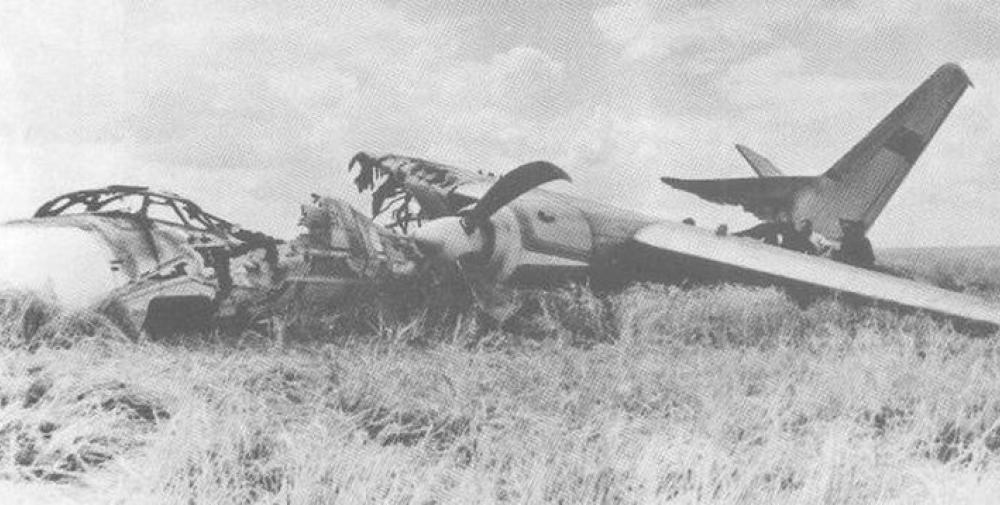
Crash of an Antonov AN-24 in Moscow
- Yekaterinburg
- Novosibirsk
- Vladivostok

- Tours to Russia
- Practicalities
- Russia in Lists
Rusmania • Deep into Russia
Out of the Centre
Savvino-storozhevsky monastery and museum.

Zvenigorod's most famous sight is the Savvino-Storozhevsky Monastery, which was founded in 1398 by the monk Savva from the Troitse-Sergieva Lavra, at the invitation and with the support of Prince Yury Dmitrievich of Zvenigorod. Savva was later canonised as St Sabbas (Savva) of Storozhev. The monastery late flourished under the reign of Tsar Alexis, who chose the monastery as his family church and often went on pilgrimage there and made lots of donations to it. Most of the monastery’s buildings date from this time. The monastery is heavily fortified with thick walls and six towers, the most impressive of which is the Krasny Tower which also serves as the eastern entrance. The monastery was closed in 1918 and only reopened in 1995. In 1998 Patriarch Alexius II took part in a service to return the relics of St Sabbas to the monastery. Today the monastery has the status of a stauropegic monastery, which is second in status to a lavra. In addition to being a working monastery, it also holds the Zvenigorod Historical, Architectural and Art Museum.
Belfry and Neighbouring Churches

Located near the main entrance is the monastery's belfry which is perhaps the calling card of the monastery due to its uniqueness. It was built in the 1650s and the St Sergius of Radonezh’s Church was opened on the middle tier in the mid-17th century, although it was originally dedicated to the Trinity. The belfry's 35-tonne Great Bladgovestny Bell fell in 1941 and was only restored and returned in 2003. Attached to the belfry is a large refectory and the Transfiguration Church, both of which were built on the orders of Tsar Alexis in the 1650s.

To the left of the belfry is another, smaller, refectory which is attached to the Trinity Gate-Church, which was also constructed in the 1650s on the orders of Tsar Alexis who made it his own family church. The church is elaborately decorated with colourful trims and underneath the archway is a beautiful 19th century fresco.
Nativity of Virgin Mary Cathedral

The Nativity of Virgin Mary Cathedral is the oldest building in the monastery and among the oldest buildings in the Moscow Region. It was built between 1404 and 1405 during the lifetime of St Sabbas and using the funds of Prince Yury of Zvenigorod. The white-stone cathedral is a standard four-pillar design with a single golden dome. After the death of St Sabbas he was interred in the cathedral and a new altar dedicated to him was added.

Under the reign of Tsar Alexis the cathedral was decorated with frescoes by Stepan Ryazanets, some of which remain today. Tsar Alexis also presented the cathedral with a five-tier iconostasis, the top row of icons have been preserved.
Tsaritsa's Chambers

The Nativity of Virgin Mary Cathedral is located between the Tsaritsa's Chambers of the left and the Palace of Tsar Alexis on the right. The Tsaritsa's Chambers were built in the mid-17th century for the wife of Tsar Alexey - Tsaritsa Maria Ilinichna Miloskavskaya. The design of the building is influenced by the ancient Russian architectural style. Is prettier than the Tsar's chambers opposite, being red in colour with elaborately decorated window frames and entrance.

At present the Tsaritsa's Chambers houses the Zvenigorod Historical, Architectural and Art Museum. Among its displays is an accurate recreation of the interior of a noble lady's chambers including furniture, decorations and a decorated tiled oven, and an exhibition on the history of Zvenigorod and the monastery.
Palace of Tsar Alexis

The Palace of Tsar Alexis was built in the 1650s and is now one of the best surviving examples of non-religious architecture of that era. It was built especially for Tsar Alexis who often visited the monastery on religious pilgrimages. Its most striking feature is its pretty row of nine chimney spouts which resemble towers.

Plan your next trip to Russia
Ready-to-book tours.
Your holiday in Russia starts here. Choose and book your tour to Russia.
REQUEST A CUSTOMISED TRIP
Looking for something unique? Create the trip of your dreams with the help of our experts.
IMAGES
VIDEO
COMMENTS
calculated that this enables a vertical wheel travel around 6 inches (150mm). 3.4 REBOUND Rebound refers to the movement of the vehicle suspension in the opposite direction of jounce. For this geometry the rebound condition is obtained when the damper retracts a length of 2.2 inches from its sag position. When the vehicle
The downward travel of the tire and wheel that extends the spring and shock absorber is called rebound, or extension. When the spring is deflected, it stores energy. Without shocks and struts the spring will extend and release this energy at an uncontrolled rate. ... As the control arm travels through jounce and rebound, the rubber portion of ...
The single wheel travel analyses with two jounce bumpers should be conducted under same configuration of free travel and maximum jounce height in each suspension model. Maximum jounce height is the distance that wheel travels from the equilibrium position to the designed highest point. Because of the different kinematic parameters of three ...
Therefore, there might be 150 mm wheel travel (normally 75 mm bump and 75 mm rebound) but filly laden, when the bump travel is most needed, there would be only 0 mm travel. Now, with self-leveling there might still be 150 mm of wheel travel, but there would always be 88 mm bump travel and 62 mm rebound travel, for example.
Review: Jounce / Rebound • Units: Jounce/Rebound position is a linear measure of the pure‐vertical distance the wheel/hub center is above or below the static (curb) ride height. Ex. a heavy cargo load may cause a rear suspension to operate at a jounce position of +1.3" - meaning the rear tires are 1.3" closer to the body than the normal
The rebound of a suspension is the maximum downward displacement at ride height, and likewise, the jounce (4th derivative of position) of a suspension is the maximum upward displacement. The upper limit of wheel-center displacement relative to the input position is 70 (mm) and the lower limit of wheel-center displacement relative to the input ...
Wheel hop oscillations are caused by road surface, tire and wheel rotational imperfections and other physical factors in the suspension. The result is that the dampers are functioning and developing unbalanced jounce and rebound forces effecting steady state tire loading and vehicle dynamics. 7.17 Travel Limiters
to the car coordinate system for different positions of jounce and rebound. Now comes the task of devising a linkage systen that will maintain this geometry (Fig. 1). ... camber, and scuff, as a function of wheel travel. A linkage 1 system for the suspension and steering system with spring type, spring attachment, and jounce bumper locations ...
c l / r Constant for the left/right body to define the type of wheel travel (jounce, rebound, no travel values: −1,1,0) ψ ˙ Magnitude of the rotational drive in r a d t i m e s t e p. The constants c l and c r can be considered as the DOFs of the mechanism. In the following, a single rebound travel of the right wheel will be discussed ...
Dual Rate Jounce Bumper Design. 2011-01-0791. Jounce bumpers are the primary component by which vertical wheel travel is limited in our suspensions. Typically, the jounce bumper is composed of closed or open cell urethane material, which has relatively low stiffness at initial compression with highly progressive stiffness at full compression.
Changes in (a) the recessio nal wheel motion and (b) the wheel track during the jounce and the rebound of the same suspension mechanisms as in Figure 5. Figure 7.
Jounce and rebound travel can be specified in terms of wheel center displacements, shock displacements, or ball joint displacements. Output. A tabular report summarizing the wheel center point and the spindle alignment points for the various positions is generated. This data can be used for tire envelope packaging studies.
Download scientific diagram | Wheel track alteration (a) and recessional wheel motion (b) during jounce and rebound for an initial solution 0, and the two solutions obtained by synthesis, 1 and 2 ...
The wheel jump range is based on the full load car, and a load case of bump movement of -50 mm~50 mm was selected for this study. A positive value represents the jounce, while a negative value represents the rebound. In jounce travel, the wheel and suspension components move upward and compress. In addition, the steering input was -500°~500°.
Nevertheless, the influences of NPR jounce bumper on the suspension mechanical performance and vehicle ride comfort were not comprehended yet. In this study, the traditional and NPR jounce bumpers were both assembled into virtual prototypes of Macpherson, double wishbone and multi-link suspensions to conduct single wheel travel virtual tests.
Jounce refers to the upward suspension travel and vertical movement that compresses the spring and shock absorber. A suspension will experience a jounce when a car comes in contact with a bump in the road. Rebound is the opposite of jounce and refers to the downward movement of the vehicle suspension. During rebound, the spring and shock ...
Rebound Bumpers. Rebound is the downward movement or extension of suspension components. There are four types of jounce bumpers supported in the truck library. Jounce Bumpers The jounce bumper is the upward movement or compression of suspension components and is used to stiffen the suspension gradually as it approaches the end of the jounce ...
With a stationary car, you will have both bump (body & frame down relative to wheels) and droop (body and frame up relative to wheels) travel. If you take this as the "zero" for measuring deflections, then one way will be positive and the other negative. So just check the signs in your results to find whether a wheel is in bump or in droop.
Much like the Elitserien Finals, we have a bit of an offense vs. defense match-up in this league Final. While Ufa let their star top line of Alexander Radulov, Patrick Thoresen and Igor Grigorenko loose on the KHL's Western Conference, Mytischi played a more conservative style, relying on veterans such as former NHLers Jan Bulis, Oleg Petrov, and Jaroslav Obsut.
Design Expectations The suspension is designed so as to satisfy following design criterion: Easy to design and manufacture Usable wheel travel of at least 50.8 mm, 25.4 mm jounce and 25.4 mm) rebound. Roll centre sufficiently above ground for good lateral stability. Small variations in camber and toe angles during the desired wheel travel. 2.2.
Burial 5 was the most unique, it was found in a coffin made of a larch trunk, with a tightly closed lid. Due to the preservative properties of larch and lack of air access, the coffin contained a well-preserved mummy of a child with an accompanying set of grave goods. The interred individual retained the skin on his face and had a leather ...
The crew was engaged in a local training flight at Moscow-Sheremetyevo Airport consisting of takeoff and landings in strong cross winds. At takeoff, the right engine was voluntarily shut down.
Zvenigorod's most famous sight is the Savvino-Storozhevsky Monastery, which was founded in 1398 by the monk Savva from the Troitse-Sergieva Lavra, at the invitation and with the support of Prince Yury Dmitrievich of Zvenigorod. Savva was later canonised as St Sabbas (Savva) of Storozhev. The monastery late flourished under the reign of Tsar ...