

How To Wire Trailer Brakes: A Step-by-Step Guide
Trailer brake light kits don’t come with wires for brakes, so you’ll need to figure it out yourself. Trailer brake light kits are a popular choice for adding safety features to their trailers. However, these kits don’t come with wires specifically for trailer brakes. Despite the fact that it may seem confusing to some people, this should not be a problem for you. Use 12 gauge wire if your trailer has two or fewer braking axles and 10 gauge wire if your trailer has three or more braking axles. To wire trailer brakes, you will first need to determine the gauge of wire required.
If your trailer has two or fewer braking axles, use a 12 gauge wire. If your trailer has three or more braking axles, use a 10 gauge wire. Find “Irrigation wiring” at Home Depot and use it for trailer brakes. Wiring a trailer brake is not known by many people. It is possible to purchase irrigation wire at Home Depot. The colors of this wire are typically black, white, and green. It is next necessary to identify the positive (112V) and negative (ground) wires. After that, it’s just a matter of crimping the right connector on each wire and attaching them to the brake switch.
Table of Contents
How to wire trailer brakes.
The process of wiring trailer brakes may seem daunting at first, but with the right knowledge and tools, it can be quite a straightforward task. So, how to wire trailer brakes? It all starts with understanding the wiring layout of your trailer. The wires for the trailer brakes usually run along the trailer’s frame and are often color-coded for easy identification.
Next, you’ll need to connect the brake controller to your vehicle. This device sends a signal to your trailer’s brakes when you apply the brakes in your vehicle. The brake controller should be wired to the battery, the brake light switch, and the trailer connector. Lastly, you need to ensure that the ground wire is properly connected. This wire completes the electrical circuit and is crucial for the proper functioning of the trailer brakes. Remember: safety always comes first!
So, if you’re not confident in your ability to wire your trailer brakes correctly, don’t hesitate to seek professional help. Wiring trailer brakes correctly will ensure not only your safety on the road but also the longevity of your trailer’s braking system.

Trailer brakes are wired 7 ways.
Most trailer brakes are wired in 7 ways, meaning there are seven different ways to wire them. The way the trailer brakes are wired will depend on the type of connector on the tow vehicle and the trailer. Diagrams are available that demonstrate how connectors can be wired for trailer brakes.
On the vehicle side, the blue wire connects to the brake controller
The blue wire is the brake control input wire, and it should be connected to the brake controller on the vehicle side. In order for the trailer to be grounded, the black wire must be connected to good ground.
The yellow wire is the electric brake output wire, and it should be connected to one of the electric brakes on the trailer.
The blue wire connects to the brake controller on the electric brakes
There are a few basic things you need to know to wire trailer brakes. The brake controller for electric brakes has a blue wire, the reverse light has a yellow wire, and the running light has a green wire.
Use 14 gauge wire for single axle trailers and 12 gauge wire for tandem trailers.
To wire trailer brakes, you need to know the right gauge of wire to use. For single axle trailers, use 14-gauge wire, and for tandem trailers, use 12-gauge wire. The next step is to identify which color wires go where.
There are six wires in total – three for the brake lights and three for the turn signals. For your trailer’s brake lights, you will typically find red, green, yellow, brown, white, and blue for your turn signals. Match each wire to its respective connector on the 7-way trailer plug. Finally, twist each wire around its connector and secure it with a crimp connector or electrical tape.

How to wire a third brake light on a trailer?
A tail light converter is required to connect a vehicle with a 5-wire system to a trailer with a 4-wire system. To connect a vehicle with a 5-wire system to a trailer with a 4-wire system, you need to use a tail light converter. This device will allow you to use the existing wiring in your car to power the brake lights on your trailer. Follow these easy steps to wire your trailer brakes:
- Locate the tail light converter near the rear of your car.
- Disconnect the black (negative) wire from your car’s battery.
- Connect the black wire on the converter to the negative wire on your car.
- Connect the red (positive) wire from your car’s battery to the positive wire on the converter.
- Connect the white (ground) wire from the converter to a good ground point on your trailer.
- Reconnect the battery in your car and test your new brake lights.
We sell and install trailer light power modules at Eyeers Trailer Hitch Center.
If you need to wire a third brake light on your trailer and are not sure how to do it, don’t worry. The specialists at Eyers Trailer Hitch Center are one of the many resources available to you. We sell and install tail light converters and trailer light power modules that will take care of this for you quickly and easily.
How to wire a tandem axle trailer with electric brakes?
Trailer brake wire kits don’t usually have the wires needed to connect them to the brakes, so you’ll need to purchase them separately. In addition, trailer brake wire kits don’t usually come with the wires needed to connect them to the brakes, and you’ll need to purchase these separately at a hardware store or online. Trailer brake wire should be at least 10 gauge and may need to be heavier for longer or heavier trailers.
To wire a tandem axle trailer with electric brakes, the first step is to determine the gauge of the brake wire. The wire should be at least 10 gauge but may need to be heavier for longer or heavier trailers. Next, remove the old brake wiring and strip the insulation from each wire using a utility knife. After that, twist each wire around its corresponding connector lug and screw them down tight. Finally, reattach the housing and test out your new brakes. The trailer junction box can provide a convenient place to tie cables into one spot.
First and foremost, when wiring a trailer, it is important to find a junction box. This can be located near the tongue of the trailer and provides a convenient place to tie cables in one spot. After this, it is necessary to identify which wires are for the brake lights and which ones are for the turn signals. The brake light wires will usually be black or red, while the turn signal wires will typically be green or yellow.
Following this, connecting each wire to its appropriate connector is necessary. The black wire will be connected to the black connector, the red wire to the red connector, etc. Finally, it is important to test the trailer brakes before hitting the road.
How to wire trailer lights and electric brakes?
Trailer brake light kits do not come with wires for brakes, so owners must improvise. Since trailer brake light kits typically do not have wires to connect to the brakes, owners must get creative. Utilizing the wiring already present in the car is one way to accomplish this. This generally involves finding a spot under the dash with good ground and running a hot lead from the brake switch up to the light.
A heavier-duty wire is recommended in some cases if the trailer has multiple braking axles. If you have more than one braking axle on your trailer, you may need a heavier-duty wire to ensure that they all work. Ensure you use the appropriate wire by consulting with a professional. Irrigation wiring is available at Home Depot that can be used instead of regular house wiring when wiring trailer lights. When wiring trailer lights and electric brakes, irrigation wiring can be substituted for regular house wiring.

How to wire trailer brakes to truck
If you own a trailer and want to be able to stop it quickly in case of an emergency, you’ll need to install trailer brakes . Using the following guide, you will learn how trailer brakes work and how they are connected to the truck’s electrical system.
- Connect the trailer brake line to the trailer’s brake controller.
- Connect the trailer brake line to the trailer’s brake controller. To connect the brake line to the brake controller, connect the appropriate connectors. Ensure that the trailer brake line is properly tensioned and that any clamps or connectors are secure.
- Test the connection by applying the brakes. The trailer’s brakes should make a loud noise if everything is working correctly, and it should stop rapidly.
- Connect the trailer’s brake light to the trailer brake controller.
The trailer brake controller is a device that will allow the driver to stop the trailer remotely. The brake light on the trailer should be connected to the controller.
How to wire electric brakes on a utility trailer?
Trailer brake light kits don’t come with wires for brakes, so a DIYer must figure it out. A heavier-duty wire (10 gauge) is necessary if your trailer has more than two braking axles or is heavy-duty in some other way. 12/2 braided irrigation wiring is a suitable wire for use on utility trailers. It’s .70 cents per foot and can be found at Home Depot.
How to wire electric brakes on a tandem axle trailer?
- Controlling the braking power of a towed vehicle is possible with an electric brake controller.
- A conventional tow vehicle wiring configuration does not allow for the use of an electric brake controller.
- Electric trailer brakes require at least 12 volts and up to 50 amps, depending on the model and weight of the trailer being towed.
- The wire gauge for electric trailer brakes varies with the trailer type; however, it tends to be thicker than regular tow vehicle wiring.
- The proper power source must be available to wire electric brakes on a tandem axle trailer.
- Elecbrakes draw sufficient power from standard trailer looms to operate electric brakes.
- Electrical systems and basic wiring skills are required to wire electric brakes onto a tandem axle trailer.
How to wire a boat trailer with surge brakes?
- Like conventional brake controllers, electric brake controllers sense the amount of pressure on the brakes and send a signal to the tow vehicle.
- Your boat’s hitch receiver can be connected to an additional side battery pack to provide power for electric brakes.
- Generally, lighter boats need less power than larger ones because their braking forces are smaller).
- To wire a boat trailer with surge brakes, first determine if your trailer has an electric brake system.
- You will need to connect the brake controller to the necessary wires if your trailer has an electric brake system.
- Connect the white wire from the braking system to the ground (the metal frame of your boat).
- To connect the braking system to the controller, connect its red and black wires, respectively.
- Connect each end of each light green wire from the controller to a corresponding light green lead on each wheel of your trailer’s brakes.
How to wire a trailer plug with electric brakes?
Trailer brake light kits do not include wires for brakes, so owners must improvise. Wiring kits for trailer brake light kits usually include turn signals and running lights, but not the brake wires. This means that owners must get creative when wiring a trailer plug with electric brakes. Most often, this means tapping into the tow vehicle’s brake light circuit, which can be done in a few different ways.
Trailer brake wire should be at least 12 gauge and can be heavier for longer trailers or ones with more serious equipment. To wire a trailer brake, you need to know your trailer brake wire gauge. This should be at least 12 gauge and can be heavier for longer trailers or ones with more heavy equipment. There are different ways of wiring a trailer brake, but the most common is using a 7-way plug.
Home Depot carries irrigation wiring, which is suitable for trailer use. You can purchase irrigation wiring at Home Depot, suitable for trailer use. The wire will have a connector that plugs into the back of the brake controller. The other end of the wire will need to be connected to the positive and negative terminals on the trailer’s electrical system.
Read Another Post: Does Tesla Have A Brake Pedal? The Answer Might Surprise You
How to wire electric trailer brakes with breakaway?
Trailer brake light kits don’t come with the wire needed to connect to the brakes on an electric trailer. Therefore, you will need a breakaway kit to wire electric trailer brakes. A breakaway kit is a mechanism that activates the trailer’s brake system when the tow vehicle separates from the trailer.
The wire needed to connect to the brakes on an electric trailer is included in the breakaway kit. If your trailer has only one braking axle, a 12 gauge wire will be suitable. For trailers with two or more braking axles, a 10 gauge wire should be used instead.
To wire electric trailer brakes, you will need to know your wire gauge. If your trailer has only one braking axle, a 12 gauge wire will be suitable. For trailers with two or more braking axles, a 10 gauge wire should be used instead.
The steps for wiring electric trailer brakes are as follows:
- remove the nut from the brake assembly and take off the dust cap;
- loosen the screw on the back of the brake assembly and pull out the brake shoes;
- remove the wire from the clip and pull out the old brake cable;
- thread the new brake cable through the hole in the brake assembly and put on a nut;
- reattach the brake shoes to the screw on the back of the brake assembly and tighten it;
- reattach the wire to the clip and crimp it closed.
The “Irrigation wiring” found at Home Depot can be used if it is properly insulated and buried. First, find an appropriate wiring kit. The “Irrigation wiring” found at Home Depot can be used if it is properly insulated and buried. Strip the insulation off the wire, then twist each wire around its corresponding terminal on the brake controller. Once the wires have been twisted, the cover must be reinstalled on the trailer connector.
How to wire a gooseneck trailer with electric brakes?
Trailer brake light kits don’t come with wires for brakes, so you’ll need to buy them separately. To wire a trailer brake, you’ll need to purchase additional supplies. Trailer brake light kits don’t come with wires for brakes, so you’ll need to buy them separately. The kit will include a power converter, which you’ll use to connect the trailer’s brakes to your car’s electrical system.
The trailer brake wire is measured in gauge and depends on the trailer setup. The setup of the trailer determines the gauge of the trailer brake wire. For a gooseneck trailer, you will need at least a 10-gauge wire for the brakes. The steps for wiring a trailer brake are relatively simple and can be completed with basic tools.
For the connection between the brake solenoid and frame ground, use 10 or 12 gauge wire. To wire a gooseneck trailer with electric brakes, you must use a 12 or 10-gauge wire. The brake solenoid and frame ground should be connected using this wire, and it is important to ensure that the connections are secure.
How to wire a trailer brake controller?
- An electric brake controller is an electronic device that helps control the trailer’s braking power.
- A trailer-side power supply configuration was not possible until the invention of Elecbrakes.
- Electric brake controllers require modifications such as additional batteries or converter boxes to function properly.
- The electrical system for trailers uses three main wires: Black, Yellow, and Gray (or Red, Blue, and Green).
- Trailer brakes use between 10-15 amps of power depending on the weight of the trailer being towed and the type of braking system being used.
- How Elecbrakes draws sufficient power from standard trailer looms to operate electric brakes.
How to wire electric trailer brakes?
Trailer brake light kits don’t come with wires for brakes, so you need to figure this out yourself. Typically, trailer brake light kits do not include brake wires, so you’ll need to do this yourself. Use the wire already running from your trailer lights to the tow vehicle, or run new wires directly from your brake controller to your trailer brakes. Regardless of your method, use a wiring diagram that is specific to your setup.
Depending on your trailer set up and needs, you can use 12 gauge wire or 10 gauge wire. You need to know what gauge of wire you need for your trailer to wire electric trailer brakes. There are two main types of trailers: those that use a breakaway system and those that do not. If your trailer does not use a breakaway system, you can use 12 gauge wire. However, if your trailer uses a breakaway system, you will need to use 10 gauge wire.
You can find irrigation wiring at Home Depot approved for automotive applications. To wire electric trailer brakes, you will need some irrigation wiring from Home Depot. This wiring is approved for automotive applications and should do the trick. Ensure that the installation is done properly by following the instructions carefully.
Frequently Asked Questions [FAQs]
1. can trailer brakes be wired backward.
No, trailer brakes cannot be wired backward. The wiring must be done correctly to ensure that the brakes are working properly and safely. If the wiring is incorrect, it can cause damage to the trailer or even lead to an accident. It is important to consult a professional if you are unsure of how to wire your trailer brakes correctly.
2. What color wire goes to electric trailer brakes?
The color of the wire that goes to electric trailer brakes depends on the brake system used. Generally, the black wire is connected to the negative terminal, and the yellow or gray (or red, blue, and green) wires are connected to the positive terminal. It is important to consult a wiring diagram specific to your setup for exact instructions.
3. What color is the electric brake wire on a trailer?
The color of the electric brake wire on a trailer will depend on the brake system used. Generally, the black wire is connected to the negative terminal, and the yellow or gray (or red, blue, and green) wires are connected to the positive terminal. Therefore, it is important to consult a wiring diagram specific to your setup for exact instructions.
4. What color wire goes to trailer brakes?
The color of the wire that goes to the trailer brakes depends on the brake system used. Generally, the black wire is connected to the negative terminal, and the yellow or gray (or red, blue, and green) wires are connected to the positive terminal. It is important to consult a wiring diagram specific to your setup for exact instructions. Additionally, it is important to ensure that all connections are secure and that the wiring is done properly to ensure that the brakes are working correctly and safely.
5. Is there a positive and negative on trailer brakes?
Yes, there is a positive and negative on trailer brakes. The black wire is connected to the negative terminal, and the yellow or gray (or red, blue, and green) wires are connected to the positive terminal. It is important to consult a wiring diagram specific to your setup for exact instructions. Additionally, it is important to ensure that all connections are secure and that the wiring is done properly to ensure that the brakes are working correctly and safely.
Wiring trailer brakes are an important part of ensuring that your trailer is safe and secure. Knowing what gauge of wire you need, what color wire goes to the electric trailer brakes, and where to find the necessary wiring are all important steps in this process. A wiring diagram specific to your setup will help ensure the installation is done properly. For example, braided irrigation wiring from Home Depot can be used for automotive applications, and 12 gauge wire is usually enough for most trailers. However, if the trailer is heavy-duty or long, 10 gauge wire may be better.
Related Posts
How Do Power Brakes Work: A Basic Explanation
How To Replace Brake Pads And Rotors In A Car? [ 10 Steps ]
How does brake fluid become contaminated?
Why Are My Brakes Pumping When I Stop? Here’s the Answer
The Causes of Locked Wheel Skids
The Importance of Maintaining Your Brakes
Snowy Driving Tips: 3 Steps To Properly Pump Your Brakes
Are Drum Brakes Hydraulic? Advantages & Disadvantage Of Drum Brakes

John D. Archer
John D. Archer is a mechanical engineer and writer based on the area of automotive accessories at brakeshub.com, A resident expert and professional, John is passionate about all things automotive and loves to share his knowledge. He has good experience in all kind of automotive accessories. He has worked as a chief mechanical engineer in some reputed automotive garage firm.

How To Wire A Trailer . . . Trailer Wiring Diagram . . . And More
So many wires . . . So many colors . . . And, so many kinds of trailer wiring connectors. Yikes! Where do I start? I need a trailer wiring diagram. And, a little more information to make sure I get all the wires right!

The wiring approach for you depends on your electrical needs. To start, every trailer needs lights – brake lights, turn signals, and tail lights. Some also need side markers and running lights. Some brakes need electricity too – to actuate electric brakes, or to disable hydraulic brakes when backing up.
The following trailer wiring diagram(s) and explanations are a cross between an electrical schematic and wiring on a trailer. We recommend these standards because they are pretty universal. That said, for specific situations, there are industrial standards for different connector styles and wire arrangements. It can get confusing, so if you don’t already have a specific standard in mind, follow these.

4-Pin Flat Connector
At a minimum, all trailers need at least 4 functions: Tail lights, Brake lights, Left & Right signals. 4 wires will give these functions, so the simplest scheme is a 4-pin connector.
The most common 4 wire connector is the 4-Pin Flat Connector as shown here. Trailers that use this are usually fairly light weight and don’t have brakes or other power accessories. It’s the most common style for “consumer” type trailers. Small utility trailers , light boat trailers, little campers, off-road trailers and many more use this traditional 4-Pin Flat connector.
Lighter Duty Trailer (No Brakes) = Use a 4-Pin Connector .
1 . White = Ground (See White Wire Notes below.) 2 . Brown = Tail Lights, Side Markers and Running Lights (See Brown Wire Notes below.) 3 . Yellow = Left Turn Signal & Left Brake Light 4 . Green = Right Turn Signal & Right Brake Light
Please see the Trailer Wiring Diagram and Connector Application Chart below. The 4-Pin connector only has the first 4 items listed. The rest you can ignore.

5-Pin Flat Connector
(Round style 5-Pin Connectors also exist.) Typically, the 5th wire (blue) is for electric trailer brakes, however, that is not always true. The 5th pin is not as standard as the first 4.
Trailers with capacity over 3000# Total Gross Trailer Weight should have brakes . That’s not mandatory everywhere, but it’s a good idea.
If a trailer has brakes, then it needs a connector with at least 5 wires. The 5th pin, a blue wire, gives power to operate the trailer brakes. (The 5th wire can also be used to disable hydraulic brakes when in reverse.)
Traditional Trailer + with Brakes = Use a 5-Pin Connector .
1-4 Wire the first 4 pins (White, Brown, Yellow, Green) just like the 4-pin connector above. 5 . Blue = Electric Brakes or Hydraulic Reverse Disable (See Blue Wire Notes below.)
In the Trailer Wiring Diagram and Connector Application Chart below, use the first 5 pins, and ignore the rest.
If your truck has a built-in 7-pin socket, but you only need 5 of the pins. Use the 7-pin connector anyway (see below), and just leave out the last 2 wires. It accomplishes the same thing for 5 wires, but with a connector that’s compatible with your truck. The 5-Pin flat connector above is nice for easy handling, but if your vehicle already has a 7-pin, just use it. It’s OK, within the standards, to leave out wires for your custom situation.
Also, worth noting, When Does My Trailer Need Brakes?

7-Pin Connector
For trailers that have a little more going on electrically, we recommend 7-pin connectors. The 2 added pins are typically for Auxiliary Power and Back-up Lights .
Expanded Use Trailer + with Brakes, Aux Power & Back-up Lights = 7-Pin Connector . (6-Pin Connectors also exist, but they are less common.)
1-4 Wire the first 4 pins just like above, and the 5th line goes to the brakes. 5 . Blue = Electric Brakes or Hydraulic Reverse Disable (See Blue Wire Notes below.) 6 . Red (or Black) = 12V Auxiliary Power (See Red Wire Notes below.) 7 . Purple = Back-up Lights (Sometimes another color.)
7-Pin Connectors like the one pictured are very common for RV’s and other bigger-ish trailers. This is the style we recommend. Other styles exist — though the pin-outs are often different. Several industrial styles are similar and definitely use different pins.
It is OK to leave a pin or two blank (unused and unconnected). For instance, looking at the trailer wiring diagram, if you want Auxiliary Power, but don’t have back-up lights, then just leave the purple wire out. A blank spot (unconnected pin) doesn’t hurt anything.
The Trailer Wiring Diagram and Connector Application Chart

Single Axle Trailer Wiring

Tandem Axle Trailer Wiring
Typical Trailer Wiring Diagram and Schematic
The 2 above wire diagrams fit the needs of most trailers. The first image shows a single axle trailer, and the second, wiring for Tandem Axles. Only the (blue) brake and (white) ground wires are different. You can expand the same conditions for more axles.
Use only the needed wires, and ignore the others. For example, if you don’t need Auxiliary Power , just leave it out. If the axles do not have brakes, then no need for that. Don’t change pin numbers or wire positions if a function is not used — just leave the pin blank (not connected).
Three Center Marker Lights
The above trailer wire diagrams don’t show the triple set of marker lights central on the front and back. Some trailers need them, and some do not. Check local ordinances for requirements.

For trailers in the USA: Typically a red 3 light set is required on the back, if the trailer is 80″ or wider – or – if over 10,000 lbs GVWR. Also, near the top in the back if taller than a certain amount. An amber 3 light set is required near the top in the front, if taller than a certain amount (usually some amount over the height of the tow vehicle). Again, check regional requirements.
Typically the 3 center marker lights are at a high point on the trailer — like above the back doors for an enclosed cargo trailer. They are fine on the back bumper of a flatbed trailer, even when the load is much higher. There are lots of extras in the laws (like top corner markings), so find out what you need for your specific trailer.
If you need the more marker lights, connect them on the Brown and White wires just like the side marker lights. (See the partial trailer wiring diagram.) These do not require additional connections at the hitch, just more wiring within the trailer. These lights should be ‘on’ basically all the time.
Side Note: Reflectors
In addition to the three center marker lights, most trailers over 80″ width require reflectors or reflective tape in alternating red and white on the sides and back. There are a lot of regulations here for height, and GVWR, especially when trailers are longer than 20′. I’m not sure about requirements outside of the USA.
Check your local jurisdiction so you can mark and light your trailer properly. Reflectors and reflector types change by jurisdiction. To some, this is overkill, but even if it is, making it right can save you a ton of legal hassle and trouble.
Trailer Breakaway Wiring Diagram

If you have electric brakes (or electric over hydraulic or some others), then it will involve the trailer wiring. Here is a partial wiring diagram to include your trailer breakaway system. Since there is a lot to discuss, we have an entire article about breakaway kits with lots more information. In the meantime, use this diagram to guide the wiring of the system. Superimpose this on the images above to see how it all comes together.
The breakaway system usually resides in, on, or under the front part of the trailer. The pin pull switch is near the hitch. The system hooks into the electrical system by connecting Auxiliary Power (Red wire +12 VDC) to keep the battery charged, the Brakes (Blue wire) to actuate the brakes, and Ground (White wire) to complete the circuit. Again, please see the article about breakaway systems for a lot more information.
Wire Routing
Where do the wires go? Now that we have the trailer wiring diagram and some definition for connectors, where do the wires actually go?
Nestle the wires into and around the frame where practical for protection. We do recommend protecting the wires with a covering of some sort. The cover is not in the trailer wiring diagram, but flexible conduit, plastic conduit, or other approaches are great. A covering does not need to be watertight, but do consider weather protection when splicing into the wires. For tips on wiring, splicing, routing and protecting, see our post on trailer lights and wires . See more in the Wire Routing Notes below.

This photo shows an ideal way to handle trailer wires. While the flexible sealed conduit nestles in and secures to the frame, it protects the wires from snags and from weather. Great job on this one.
Trailer Wiring Diagram Notes
Many different sizes of wires are available. Typically wire sizes are list by “Gauge” — a smaller number is a thicker wire. We recommend 16 gage and larger for lighting. Then, for power hungry things like brakes, use a thicker wire size, like 14 gauge or 12 gauge. Same for Auxiliary Power.
Lighting circuits with low power lights like LED’s have low power requirements, so even with a lot of lights, they don’t use much power. For lights, a relatively small wire gage works. We still recommend 16 gage and larger, not so much because of the power requirements, but because the wires are stronger, more robust, and have more surface area for splice connections. It’s worth the small additional expense.
We recommend sealed and submersible LED lights for just about everything. Yeah, most trailers are never submersed, but almost all get very wet like in heavy rain or when washing. Pay the extra dollar or two and get the higher quality lights. Trouble free operation with higher quality lights make them worth it.
White Wire Notes:
The White Wire is the “Ground” or “Negative” wire connecting to the vehicle battery “minus” side. The trailer wiring diagram shows this wire going to all the lights and brakes. Also, it must connect with things (if included) that use the Aux Power and Back-up lights too.
Some trailer builders just connect this wire to the frame, then connect the ground from all the other lights and accessories to the frame as well. While this usually works, the ground portion of the circuit is often the root of trailer electrical problems. To avoid some of those issues we recommend running the white wire with all the others and connecting the ground from each light directly to the White. It is a little more work, but it can save big headaches later.
We also recommend connecting the white wire directly to the trailer frame (in addition).
Size: This wire should be at least as big as the largest wire in your harness. If only lights are in the circuit, and the lights are LED (low power), then a small white wire is acceptable. However, if you have electric brakes or auxiliary power, this wire must be larger.
Brown Wire Notes:
The Brown Wire goes to the lights that are always ON as you travel. These are the running lights, the low intensity portion of the tail lights, side markers, and corner markers. Also, if used, the sets of 3 lights central in front and back of the trailer. Check local laws for requirements on which lights your trailer needs.
While the typical sets of 3 lights central in the trailer are not in the above trailer wiring diagram, they are important in some situations. They are not normal for smallish DIY utility type trailers. However, if you need them or want them, the brown wire feeds them too (and the white for ground). Tiny Houses may or may not need the 3 lights, but again, check local laws.
Size: The Brown wire only feeds power to lights, so size it for the power requirements of your lights. For a utility trailer, that is probably not much power, so a smaller gage is OK. For a large enclosed trailer with lots of running lights, consider a larger gage.
Yellow and Green Wire Notes:
The two wires, Yellow and Green, handle double duty for function. They activate lights for both Turn Signals and for Brakes. It’s the same physical “light” at the rear of the trailer, but it serves 2 functions. The wiring in the vehicle sorts out how those signals are sent.
The Yellow wire handles the Left side – left as you look at the back of the trailer. (Or, in a different way of thinking, left as you are sitting in the driver’s seat of the tow vehicle.) The Green wire handles the Right side. See the above trailer wiring diagram for a visual.
Size: See the above discussion about Wire Size. We recommend 16 gage and larger for lights, and we recommend LED lights.
Blue Wire Notes:
Typically, the blue wire is for electric trailer brakes, however, this wire is not as standard as lights and ground.
For electric brakes, on the vehicle side the blue wire goes to the brake controller. Many styles of brake controllers are available, so find one that works for your vehicle. On the trailer side, the blue wire goes to the brakes and breakaway circuit. (See the trailer wiring & breakaway diagrams above.)
Here are some other ways the blue wire is sometimes used.
- Some trailers with surge hydraulic brakes use this 5th pin to disable the brakes when the vehicle is reversing. This is not in the trailer wiring diagram above. If you do this, then connect the blue wire to the reverse lights on the tow vehicle side, and be sure to note what you’ve done. Better yet, use a purple wire instead, and label it.
- Some places label the 5th pin for “Reverse Lights”. If you do that, then make sure to note it on the trailer, because it can cause a lot of trouble if connected wrong.
Just be careful when using a 5-pin connector. Make sure the car wires match functions of the trailer.
Compatibility Case Example: To solve issues with tow vehicle wiring that is different from my trailer (for instance when a friend wants to borrow it), I simply have a short adapter that connects the 5-pin harness to a 4-pin vehicle and the trailer goes without brakes. It works because the trailer is not big or heavy – and with a light load it does not require brakes. I just tell the borrower the load capacity is 3000# (even though true capacity is 5000#.) Another way is to have an adapter that goes from the trailer 5-pin to a standard 7-pin (with 2 wires left blank). That way the trailer brakes are ready, if the tow vehicle has a 7-pin connector.
Size: Don’t skimp on wire size for your brakes. For a single axle, 14 gage is good, but for tandem axles, use 12 gage wire.
Red Wire Notes:
The pin for Aux Power is usually with a Red Wire, but sometimes it’s different like Black. Sometimes we call it ‘Aux Power’ or ‘Auxiliary Power’ or ‘Accessory Power’ or ‘Batt 12V+’. Whatever the name it connects to the tow vehicle positive, DC power. Typically, auxiliary power is for charging the Breakaway battery, RV batteries, interior lights, power for accessories, etc.
The extent of routing for the Red wire is not on the above Trailer Wiring Diagram because it is optional, and different for every trailer. In the Breakaway wiring section, the schematic there shows how the Breakaway battery box connects to the Red. That maintains the battery charge.
If you don’t need separate power on the trailer, just leave that pin out. If you do use it, then be sure you protect the vehicle electric system from shorts (use a fuse or circuit breaker). Also, it’s good to protect the system from completely draining the tow vehicle battery.
Size: Use a wire size appropriate for the power demands. If it’s just for charging the breakaway battery, then 16 gage is fine. If you’re powering up more batteries or lights in the trailer, then use 14 or even 12 gage. Don’t overload this wire. If you do need large amounts of auxiliary power, use a generator or install special wiring from the vehicle alternator.
Wire Routing Notes:
The trailer wiring diagram above gives one flavor for routing direction – starting at the tongue connector, then wrapping around the trailer. Other people suggest splitting the wires near the tongue, then routing down both sides — Right and Left specific. Either approach is fine.
While wire routing is a personal preference, I like the wrap around approach a little more because it makes a ‘trunk’ that distributes power as it goes. It also keeps the wires all in one group as they traverse along the tongue so they are easier to protect. The amount of wire is almost identical for both the split and wrap around approach.
Protecting The Wires:
Hollow frame members are often the route for wires. For instance, if the frame is constructed of rectangular steel tube , then putting wires down the tube seems like an easy way to protect them. While this is true, it also means that you can’t cap (seal) the ends of the tube to keep moisture out. That’s a trade-off to consider, but it does not have to be all or nothing. On my last trailer, I routed the wires through the tongue tube, then outside the main frame members (tubes) so they can seal. Wire and light connections are outside of the frame tubes under the trailer bed.
When running wires consider the possibility of changes down the road. If you’re sure changes will never happen, button things up super tight. If you think changes might happen later, then leave access to the wires. For example, for a little camper, you might think Aux Power is on the “I’m never going to use that” list. But in a few years, you might find the solar doesn’t always cut it, and Aux Power is suddenly desirable. By leaving access to the wire routing, running the additional wire is not so difficult. Food for thought.
Frugal Living
Health & beauty, holidays & activities.
- Budget New Year's Eve
- Budget Christmas
- Budget Valentine's Day
- Budget Halloween
- Budget Thanksgiving
- Budget 4th July
- Meal prep ideas
- Instant pot
Minimalist Living
- Decluttering
- Capsule wardrobes
Money Management
- Alternative Living Spaces
- Storage & organization
- Campers and RV's
- Conversions
Off the Grid
- Micro Apartments
- Shipping Container Homes
- + Post a new Story
- Saved Stories
- Account Settings
- Support • Privacy
How to Fix Broken Trailer Brake Wiring: A Step-by-Step Guide

When was the last time you did an inspection on your trailer? Do you check for things that are not right? What I mean by that is, do you go physically underneath the trailer, and check your trailer brake wiring?
I did that today and I discovered a major brake fail.
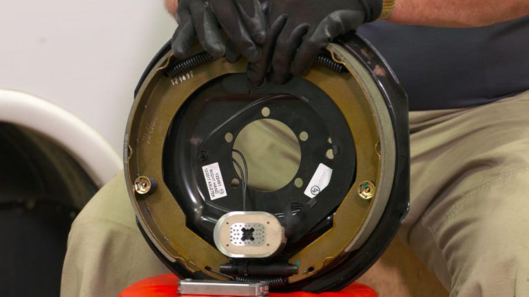
We have electric brakes on our 2021 Grand Design Imagine 2500RL. When I did my inspection underneath the frame, I discovered that there were two wires that were severed, and I can tell that they've been severed for a long time.
It could have been caused by a piece of debris on a road. Who knows? We could have run over a rock piece of wood on the freeway and cut those wires.
I was actually really surprised to see that it happened, but so important to get it fixed. I remember on our trip when I had to hit the brakes a few times, my brakes were skidding. I wonder if it was because only one of the electric brakes on one of the axles was working and the rear axle wasn't working.
Unbeknownst to me, we were probably running our trailer with only one set of trailer brakes. So today we're going to go through how to fix trailer brakes.

I'm going to use the wire stripper but I don't have my crimpers to crimp the butt connectors with a shrink tube. I also have zip ties to zip tie the wire to the axle, a lighter, and some black electrical tape.

As you can see, both a white wire and a green wire are disconnected, plus the zip tie that held the wires to the axle is gone.

First, I need to remove the metal crimp, so I cut it out.

Next, I snipped the ends of the wires I want to reattach and then stripped the wire ends.

Once the tip of the wire has been stripped, I feed one end into a butt connector, and crimp it into place so it's nice and snug.

Then, I do the same with the green and brown wires. Feed them into the opposite end of the butter connector.

Take a lighter and hold it up to the butt connector to shrink it. Once it's shrunk, tug on it. Make sure it's nice and strong.

Now for me, as a little bit of added protection, which I'm always usually overkilling, I like to wrap the butt connector with some black electrical tape.
Then, it's onto the other wires. I just do exactly the same as the first three.

Now it's time to attach the wires to the axle. Got to give enough room for this to move within the confinement of the suspension, but I don't think it's going to move that much. But anyway, let's do a zip tie there. I'm feeling like I want to almost double zip tie, to be honest with you. I'm putting it behind the axle in case a rock hits it.

To test the brakes, connect them, lift up the truck with the jack underneath it, spin the tire, and then hit the brakes. Make sure it stops.
How to fix trailer brake wiring
Boom! Brakes are working! That is great news. So where the brakes weren't working, they're working now. That is how you fix your trailer brake wiring.
Let me know if you found this useful in the comments below.
Join the conversation
More stories.

Beautiful and Green: Runaround Sue -- 1961 Vintage Airstream Safari Renovation
Renovated Mobile Home - Landfill Save - MH4
5 Camper Storage Hacks
Frugal Homemaking Tips | Ideas for Saving Money Every Day
DIY Camper Waste Tank Cleaner
Best Tips to Save Plants Over Winter
Bathroom Declutter: 15 Things You Don't Need in Your Bathroom
15 Simple Clutter Rules For a Minimalist Lifestyle at Home
5 Things You Can Safely Clean In Your Washing Machine
10 Surprising Items Your Kitchen Doesn't ACTUALLY Need

8 Cool Reasons to Save Coffee Grounds That You Probably Don’t Know
Did You Know You Can Freeze This?
10 Clever Hacks Using Tide Pods You Never Knew About!

What to Buy in Bulk From the Dollar Tree Online
10 Huge Walmart Shopping Mistakes That Everyone Makes

10 Totally Unexpected Vaseline Hacks for Your Home

5 Easy High-End Dollar Tree DIYs For Your Home

10 Simple Ways to Lower Your Electric Bill

How to Troubleshoot Common Travel Trailer Electrical Issues
Electrical issues are a common problem for travel trailer owners. In this blog post, we’ll discuss how to troubleshoot and resolve some of the most common travel trailer electrical problems.
Table of Contents
Diagnosing and Fixing Travel Trailer Battery Charging Problems
Travel trailer battery charging problems can lead to a dead battery and loss of power. To diagnose and fix battery charging issues:
- Inspect the battery for visible damage, bulging, or leaks.
- Check the battery terminals for corrosion and clean them if necessary.
- Test the battery voltage using a multimeter (Amazon) .
- Ensure the converter is properly charging the battery.
- Replace the battery if it fails to hold a charge.
Understanding and Resolving Travel Trailer Converter Issues
The travel trailer converter is responsible for converting 120V AC shore power into 12V DC power for the trailer’s electrical system. Common converter issues include:
- Overheating
- No output voltage
- Low output voltage
- Intermittent power
To resolve converter issues, check for loose connections, inspect the converter’s fuses, and ensure proper ventilation. If problems persist, consider replacing the converter.
Troubleshooting Travel Trailer Power Inverter Failures
A power inverter converts 12V DC power from the travel trailer’s battery into 120V AC power for appliances and outlets. Inverter issues may include:
To troubleshoot inverter issues, inspect the wiring connections, check the inverter’s fuses, and ensure proper ventilation. If necessary, replace the inverter.
Dealing with Travel Trailer Electrical Shorts and Blown Fuses
Electrical shorts and blown fuses are common travel trailer issues that can result in power loss. To resolve these issues:
- Identify the affected circuit by checking the fuse panel.
- Inspect the wiring for damage, frayed insulation, or loose connections.
- Replace any blown fuses with the correct amperage.
- If the issue persists, consult a professional for further troubleshooting and repair.
How to Identify and Repair Faulty Travel Trailer Wiring Connections
Faulty wiring connections can cause a variety of electrical issues in travel trailers. To identify and repair wiring issues:
- Inspect the wiring for visible damage, fraying, or corrosion.
- Test for continuity using a multimeter.
- Repair or replace damaged wiring and connectors as needed.
Tips for Resolving Travel Trailer Lighting Problems (Interior and Exterior)
Travel trailer lighting problems can range from a single non-functioning light to a complete loss of lighting. To resolve lighting issues:
- Check for blown fuses in the fuse panel.
- Inspect the bulbs for damage or burnout and replace if necessary.
- Test the light switch or fixture for proper voltage using a multimeter.
- Inspect wiring connections and repair or replace as needed.
Diagnosing and Fixing Travel Trailer 12V System Malfunctions
12V system malfunctions can result in loss of power to various travel trailer components. To diagnose and fix 12V system issues:
- Check the battery for proper voltage and charge.
- Inspect the converter for proper output voltage.
- Test fuses and circuit breakers in the 12V system.
- Inspect and repair any damaged wiring or connections.
Troubleshooting Issues with Travel Trailer Solar Panel Systems
Solar panel systems can provide supplemental power for travel trailers. Common issues include:
- Reduced power output
- No power output
- Damaged panels
To troubleshoot solar panel issues, inspect the panels for physical damage, clean the panels to remove dirt and debris, and check the connections between the panels and the charge controller. If necessary, consult a solar panel professional for further assistance.
Take a look at our article on: Installing Solar Panels On Your RV: A Step-By-Step Guide
How to Address Travel Trailer Generator Electrical Problems
Travel trailer generators can develop electrical issues, such as:
- Low power output
To address generator issues, inspect the generator for loose connections, ensure proper fuel levels and quality, and perform routine maintenance according to the manufacturer’s guidelines. If problems persist, consult a generator technician for further assistance.
Understanding and Fixing Travel Trailer GFCI Outlet Failures
Ground Fault Circuit Interrupter (GFCI) outlets protect against electrical shocks in wet or damp areas of the travel trailer. GFCI outlet failures can result in a loss of power or potential safety hazards. To fix GFCI outlet issues:
- Press the “Reset” button on the GFCI outlet.
- Test the outlet using a GFCI tester (Amazon) .
- Inspect the outlet wiring and connections.
- Replace the GFCI outlet if it continues to fail.
Travel Trailer Circuit Breaker Tripping: Causes and Solutions
Circuit breakers protect travel trailer electrical systems by tripping when a circuit is overloaded. To resolve circuit breaker issues:
- Identify the affected circuit and unplug any connected devices.
- Reset the circuit breaker by switching it off and then back on.
- Reconnect devices one at a time to identify the cause of the overload.
- If the issue persists, consult a professional for further troubleshooting.
How to Troubleshoot Travel Trailer Appliance Electrical Issues
Travel trailer appliances, such as refrigerators, air conditioners, and microwaves, can develop electrical issues. To troubleshoot appliance issues:
- Check for blown fuses or tripped circuit breakers.
- Inspect the appliance’s power cord and connections for damage.
- Test the appliance’s power source using a multimeter.
- Consult the appliance’s owner’s manual for specific troubleshooting steps.
Identifying and Resolving Travel Trailer Electrical Grounding Problems
Proper electrical grounding is essential for travel trailer safety. Grounding issues can cause:
- Electrical shocks
- Appliance malfunctions
- Power fluctuations
To resolve grounding issues, inspect the travel trailer’s grounding connections for damage or corrosion, and repair or replace as needed.
Tips for Addressing Travel Trailer Slide-Out Electrical Malfunctions
Travel trailer slide-outs can experience electrical malfunctions, such as:
- No power to the slide-out motor
- Stuck or slow-moving slide-outs
To address slide-out electrical issues, check for blown fuses or tripped circuit breakers, inspect the slide-out motor and wiring for damage, and consult the owner’s manual for specific troubleshooting steps.

How to Diagnose and Fix Travel Trailer Power Surge Damage
Power surges can damage travel trailer electrical systems and appliances. To diagnose and fix power surge damage:
- Inspect appliances and electronics for signs of damage.
- Test the affected devices using a multimeter.
- Replace damaged fuses, circuit breakers, or components as needed.
- Consider installing a surge protector (Amazon) to prevent future surge damage.
Troubleshooting Travel Trailer Electrical Issues Related to Water Damage
Water damage can cause a variety of electrical issues in travel trailers, such as:
- Short circuits
- Corrosion of wiring and connections
To troubleshoot water damage-related electrical issues:
- Identify and repair any water leaks or sources of moisture.
- Inspect wiring, connections, and appliances for signs of water damage.
- Replace or repair damaged components as needed.
- Thoroughly dry the affected areas before restoring power.
Dealing with Travel Trailer Power Distribution Panel Problems
The power distribution panel is the central hub for a travel trailer’s electrical system. Common panel issues include:
- Blown fuses
- Tripped circuit breakers
- Loose or damaged wiring connections
To resolve power distribution panel issues, inspect the panel for signs of damage, replace blown fuses or reset tripped circuit breakers, and tighten or repair any loose or damaged wiring connections.
How to Troubleshoot and Repair Travel Trailer Electric Brake Issues
Travel trailer electric brake issues can compromise safety and performance. Common electric brake problems include:
- Weak or inconsistent braking
- No brake activation
- Overheating brakes
To troubleshoot and repair electric brake issues:
- Inspect the brake wiring and connections for damage or wear.
- Test the brake controller for proper function using a brake controller tester (Amazon) .
- Check the brake magnets and replace them if necessary.
- Inspect and adjust the brake shoes and drums as needed.
Understanding and Fixing Travel Trailer Awning Motor Electrical Problems
Electric awning motors can experience electrical issues that prevent the awning from extending or retracting properly. To fix awning motor electrical problems:
- Check for blown fuses or tripped circuit breakers related to the awning motor.
- Inspect the awning motor wiring and connections for damage or wear.
- Test the awning motor switch for proper function using a multimeter.
- Replace the awning motor if it fails to operate correctly.
By understanding and addressing these common travel trailer electrical issues, you can ensure a safe and enjoyable experience on the road. Regular maintenance and inspection of your travel trailer’s electrical system will help prevent problems and keep your adventures running smoothly.
Good luck, and happy camping!
Check out our article on: How To Maintain and Repair Your Travel Trailer’s Propane System
Please keep in mind that we may receive commissions when you click our links and make purchases. However, this does not impact our reviews and comparisons. We try our best to keep things fair and balanced, in order to help you make the best choice for you.
As an Amazon Associate, I earn from qualifying purchases.

Troubleshooting Trailer Brakes: Symptoms, Causes and Remedies
- Description
In this quick video lesson, RV repair expert Dave Solberg walks you through the process of troubleshooting trailer brakes to determine why they might not be functioning properly. As a general rule of thumb, RVs should be thoroughly inspected at least once per year, depending upon frequency of use and miles traveled. A comprehensive inspection includes the wheels, tires, and brakes.
Although you should already be checking the status of your trailer’s brakes on a regular basis, you might notice one of many issues between inspections. Dave has several suggestions to solve the problems you could encounter with your electric RV brakes. Follow along as he goes step by step through the process.
What to look for when troubleshooting trailer brakes
To help you figure out what’s wrong with your trailer’s brakes, Dave refers to Dexter’s comprehensive guide for troubleshooting. This guide lists each of the symptoms, causes and remedies to common problems you might encounter with your brakes.
Most RV braking systems vary slightly in mechanics and technical aspects, but they all tend to have similar symptoms. For instance, as far as electrical issues, the problem could lie in the connection between your brakes and the controller in your tow vehicle. You should ensure that voltage is flowing from the controller to the pigtail to each wheel’s brake magnets. If not, you might need to increase the controller’s setting (graded 1-10) or adjust the pads for better contact with the wheel well.
There are other possible electrical issues that you should look for when troubleshooting trailer brakes. Maybe you’ve noticed improper synchronization between the controller and the brakes. Easily fixed. It could also be a blown fuse inside the trailer, or a short in one or more of the wires. Wires can come loose from debris, and fuses blow all the time!
Other things to check
As far as the individual brakes, you should inspect for reduced friction on the brake pads. This process, called glazing, is the smoothing of pads due to excessive heat. You can either sand them up to regain grip or have them replaced if they’re too far gone. And most importantly, Dave always recommends having your loaded vehicle weighed for Gross Vehicle Weight Rating and Gross Axle Wheel Rating. To get the smoothest ride and longest lifespan for your vehicle, you want to come in under for both of those numbers.
In addition to these tips to troubleshooting trailer brakes, Dave introduces several other possible symptoms, causes, and solutions to get your braking system fixed up . If you’re unsure what’s going on with your brakes, consider taking your vehicle in to see a certified technician. When in doubt, be safe!
Explore videos by Dave Solberg

You may be interested in
Premium Membership
Unlock exclusive member content from our industry experts.
- 24/7 Access to Premium RV Maintenance Videos, Travel Inspiration, and Lifestyle Tips
- Step-by-Step Instructional Demos, Projects, and Guides
- 50% Off Video Downloads Purchased in the RV Lifestyle & Repair Shop
- Access to Ask the Expert Program
- 2 Full-Length Video Downloads to Watch Offline
Gold Membership
Get everything included in Premium plus exclusive Gold Membership benefits.
- 9 Full-Length Video Downloads to Watch Offline
- 2 Full-Length RV Repair Classes to Keep for Life
- Discounts on Purchase-to-Own Content in the RV Lifestyle & Repair Shop
- Exclusive GOLD LIVE Streaming Events
Username or email *
Remember me
Lost your password?
Privacy Policy
.png "travel trailer brake wiring")
FREE SHIPPING ON $150+ ORDERS
RV Trailer Wire Diagrams: How to Wire Your Trailer the Right Way
Learn how to wire your trailer so you can seamlessly use all electric appliances in your trailer as well as tow the trailer effectively.

Embarking on a road trip adventure in your RV is exciting, but don’t forget to make sure your RV’s systems are in order before hitting the road! One critical aspect often overlooked is the correct wiring of your recreational vehicle. A well-wired trailer not only promotes safety on the road but also ensures that your lights, brakes, and signals function seamlessly.
From powering appliances to maintaining essential safety systems, understanding the ins and outs of RV wiring is a must for any enthusiast. Whether you're a seasoned traveler or a novice hitting the open road, your RV’s electrical system is complex and requires attention. Lucky for you, we have covered everything you need to know and get in order before you set out. Take a read below so that you can navigate the process with confidence and enjoy a stress-free journey ahead!
The Importance of Proper RV Wiring
Proper RV wiring is more than just a technicality; it's the backbone of a safe and functional road trip experience. Without accurate and well-maintained wiring, you risk a host of problems that can quickly turn your adventure into a nightmare. Safety comes first, and correctly wired systems ensure that crucial functions like lights, brakes, and electrical appliances work seamlessly. This not only safeguards you and your fellow travel companions but also other motorists on the road. Other than that, efficient wiring maximizes energy usage, saving power and ultimately extending the lifespan of your RV's components.
Different Types of RV Trailers and Wiring Needs
The diverse world of RV trailers encompasses a wide range of options, each with unique wiring needs. When it comes to wiring requirements, travel trailers are a popular choice for those who prefer versatility and mobility. A typical travel trailer often utilizes a 30-amp RV 7-way trailer wiring diagram to handle essential systems like lighting, brakes , and appliances while smaller trailers operate with a 5-wire trailer connector and even a 2-wire trailer connector. These trailers are designed to be compact and lightweight, making them suitable for a 30-amp electrical supply.
On the other hand, fifth-wheel trailers cater to a more luxurious camping experience , requiring a robust 50-amp RV trailer plug wiring diagram to accommodate larger appliances, air conditioning units , and advanced entertainment systems. The substantial power requirements of these trailers make the 50-amp RV plug a vital component in ensuring all amenities function smoothly.
Additionally, the specific wiring requirements can vary based on the age and make of the RV trailer. Older models may require updates and renovations to bring their wiring systems up to modern safety and technology standards. Vintage Airstream trailers, for example, often need comprehensive overhauls to support modern conveniences. In contrast, newer RV trailers are typically equipped with advanced RV trailer wiring harnesses and the usual 2 trailer hitch ball mount, designed to handle high-tech devices and provide enhanced convenience.
Whether you're towing an older model or a brand-new luxury RV trailer, understanding the distinct wiring needs is crucial to ensure your trailer is not only functional but also optimized for the level of comfort and convenience you desire during your travels. So, considering the type of RV trailer and its age is vital in determining the wiring requirements, whether it's a 7 pin RV trailer wiring diagram, 4 wire trailer connector, or a 5 wire trailer wiring to 7 pin setup.
Basic Components of RV Trailer Wiring Systems
Before diving in, it is important to know just what you are dealing with. These components collectively form the backbone of an RV trailer's wiring system, whether you're dealing with a 30 amp RV wiring diagram or a 50 amp RV plug wiring diagram. Understanding these elements is essential for maintaining, troubleshooting, and ensuring the safe operation of your RV trailer during your travels. Give a quick read below to get a gist of the components in the system!
7-Way Connector:
The 7-way connector is a pivotal component that links the trailer's wiring to the tow vehicle. It consists of seven pins, each serving a specific purpose. These pins are numbered and color-coded for easy identification, ensuring the proper connection of power and signals between the RV trailer and the towing vehicle. One essential function of a 7-pin trailer plug is to charge the RV’s battery as it's being towed, ensuring that the trailer's electrical system remains operational.
Wiring Harness:
An RV trailer wiring harness is a network of cables and wires that extends throughout the RV trailer. It includes various wires for lighting, brakes, battery charging, and auxiliary power. This harness ensures a systematic and organized distribution of electricity from the 7-way connector to the trailer's components.
Trailer Wire Adaptor Connector:
A trailer wire adapter connector is a necessary component for the RV trailer wiring system as it helps to bridge the gap between different towing vehicles and trailers. This device ensures compatibility between various 2-wire trailer connectors and the towing vehicle's wiring.
Hitch Ball:
The hitch ball is crucial because it's the direct point of connection between the tow vehicle and the RV trailer. It ensures a secure link, allowing the trailer to be towed safely and effectively. Selecting the correct ball size for trailers is imperative, even for gooseneck trailers for safe towing as an incorrect size can lead to an unstable connection and potential accidents on the road.
Ball Mount:
A 2-trailer hitch ball mount plays a vital role in maintaining the level of the trailer when attached to the tow vehicle. Proper leveling is essential for safe towing because it ensures that the trailer's weight is distributed evenly, preventing issues like swaying or excessive strain on the tow vehicle's suspension.
Auxiliary Power Circuit:
The auxiliary power circuit in the 7-way connector is a versatile feature. It allows the trailer to draw power from the tow vehicle for various purposes, such as running interior appliances or charging auxiliary batteries. This added flexibility ensures that the trailer can meet a range of power requirements.
Ground Wire:
A ground wire is a fundamental part of the RV trailer wiring system. It connects to the metal frame of the trailer, creating a secure ground path for the electrical system. Proper grounding minimizes the risk of electrical issues, ensuring that the various components and systems function reliably and safely.
A Guide to Wiring Your Trailer the Right Way
With so many components and wires to keep track of, you won’t be the only person who gets confused. Follow our step-by-step guide below to make better sense of the process. By understanding the specific wiring needs of your trailer, you can wire your trailer correctly, whether it's a 5-wire trailer wiring to 7-pin setup or any other configuration. Here's a 10-step guide you on how to wire a 7-pin trailer plug the right way:
Step 1: Gather Tools and Materials
Ensure you have all the necessary tools, including wire cutters, crimping tools, heat shrink tubing, and materials like the appropriate gauge wire, a 5-pin trailer plug or a 5-pin to 7-pin trailer plug, and other trailer hitch ball accessories.
Step 2: Determine Wiring Needs
Understand your trailer's wiring needs based on its type and size. This could involve a travel trailer with a 30 amp RV wiring diagram or a travel trailer with a 50 amp RV plug wiring diagram, depending on the trailer's electrical demands.
Step 3: Locate the 7-Way Connector
Identify the ideal location on your trailer for mounting the 7-way connector. This should be easily accessible and near the rear for connection to the tow vehicle.
Step 4: Prepare the Wires
Trim and strip the wire ends for clean connections. Ensure you use the correct wire colors based on standard coding: red (12V power), green (right turn/brake), yellow (left turn/brake), white (ground), and so on.
Step 5: Connect the Wires
Connect the stripped wires to their respective pins on the 7-pin trailer plug. Use crimp connectors for a secure connection, ensuring a snug fit and good conductivity.
Step 6: Protect the Connections
Slide heat shrink tubing over the crimped connections and apply heat to seal and protect the wires from moisture and corrosion. Ensure a watertight seal.
Step 7: Secure the Wiring
Use zip ties or clamps to secure the wiring along the trailer frame. Prevent loose wires that could be damaged or drag on the road.
Step 8: Ground Wire Installation
Attach the white wire, which is the ground wire, securely to the trailer frame. Ensure a clean and rust-free connection point.
Step 9: Test the Wiring
Before hitting the road, test all the connections. Verify that all lights, turn signals, brakes, and other electrical components work correctly. A trailer wire adapter connector can be helpful for compatibility with your tow vehicle's wiring.
Step 10: Secure the 7-Way Connector
Mount the 7-way connector securely in its designated location on the trailer. Ensure it is protected from the elements and won't become disconnected during travel.
RV Trailer Wiring Diagrams
Here are some common trailer wiring diagrams for your reference.
RV 7 Way Trailer Wiring Diagram

4 Wire Trailer Connector Diagram

RV 7 to 6 Trailer Wiring Diagram

RV 7 to 5 Trailer Wiring Diagram

RV 7 to 4 Trailer Wiring Diagram

RV 4 to 4 Trailer Wiring Diagram

Common Mistakes to Avoid in Trailer Wiring
If you are new to understanding the wiring system of your RV, you are bound to make some mistakes. Ensuring proper trailer wiring is essential for safe and trouble-free towing. To help you avoid common mistakes, here are five pitfalls to steer clear of when working on your trailer's electrical system:
Inadequate Grounding:
A frequent mistake in trailer wiring is neglecting the importance of proper grounding. Failing to establish a solid ground connection between the trailer's wiring and the frame can lead to erratic electrical behavior. Ensure that the white wire (ground) is securely attached to a clean, rust-free part of the trailer frame, providing a reliable path for the current to return to the battery.
Incorrect Wire Sizing:
Using the wrong gauge of wire is another common error. The wire size should match the electrical load and distance it needs to travel as an inadequate wire gauge can lead to voltage drop and insufficient power to your trailer's components. To know what size wire you need for the trailer wiring systems, check the manufacturer's recommendations or refer to the RV wiring diagram.
Neglecting Weatherproofing:
Failing to protect your connections and wiring from the elements is a recipe for trouble. Exposed wires and connections can quickly corrode or short-circuit when exposed to moisture. Use heat shrink tubing or electrical tape to seal and protect your connections, ensuring they remain dry and corrosion-free.
Poor Cable Management:
Untidy and loosely secured wiring is not just unsightly; it can also be dangerous. Wires that dangle or drag on the road can get damaged or pose a safety hazard. Use zip ties or cable clamps to secure the wiring along the trailer frame, keeping it away from moving parts and road debris.
Incorrect Wiring Order:
Reversing the wiring order or improperly connecting the wires to the trailer plug is a common mistake. This can result in erratic lighting, non-functional brakes, or even electrical damage to your tow vehicle. Always consult a 7-pin RV trailer wiring diagram or the manufacturer's guidelines to ensure the proper connection of wires to the trailer plug.
Safety Tips to Keep in Mind When Wiring Your Trailer
Remember, at the end of the day, you are dealing with electrical wires and a complicated system. It is prone to accidents, sparks, unseen issues, and a multitude of other problems. By following these 5 safety tips when wiring a trailer, you can significantly reduce the risk of accidents.
Disconnect Power Sources:
Before starting any wiring work, ensure that all power sources are disconnected. This includes unplugging the tow vehicle, disconnecting the trailer from the vehicle, and disconnecting any batteries that may be part of the trailer's electrical system. This precaution eliminates the risk of electrical shock or short circuits during the installation or repair process.
Eye Protection and Gloves:
Wearing appropriate personal protective equipment is crucial. Safety glasses or goggles can protect your eyes from potential debris and wire ends. Additionally, insulated gloves are essential to minimize the risk of electrical shock while working with wires and connections.
Work in a Dry Environment:
Wiring tasks should be performed in a dry environment. Moisture and wet conditions can lead to electrical hazards, so it's essential to avoid working on your trailer's wiring during rainy weather. If you must work in damp conditions, take extra precautions to keep all connections dry and use waterproof sealants.
Use the Right Tools and Materials:
Using the proper tools and materials is essential for safety. Make sure your wire cutters, crimping tools, and connectors are in good condition and appropriate for the job. When making connections, use heat shrink tubing or electrical tape to insulate and protect the wires, and choose high-quality components and materials to ensure a reliable and safe trailer wiring system. Also make sure to learn beforehand what size wire you need for the trailer wiring and what size ball you need for your trailer, especially for a gooseneck trailer, so that you don’t encounter these issues after you start wiring your trailer.
Double-Check Your Work:
After completing the wiring, it's crucial to double-check your work for any loose connections, exposed wires, or potential issues. Test all the trailer's lights, brakes, and signals to ensure they function correctly. It's better to identify and rectify any issues before hitting the road, reducing the risk of accidents or breakdowns during your journey.
In the world of RV traveling, trailer wiring and safety are paramount. Your guide to a comfortable journey begins with ensuring a solid, secure electrical foundation. With proper grounding, the right tools, and a vigilant eye for detail, you're on your way to a world of comfort and adventures.
- How To's
Recent Posts
10 Travel Trailer Renovation Tips on a Budget
Backing Up a Trailer: A Guide
Mounting a TV in an RV: All You Need to Know
DISCLAIMER: Some links in our blog posts may be affiliate or paid links. We may earn a commission if you click on these links and make a purchase. Your support through these links helps keep our blog running. Thank you!

4 Common Problems in a Trailer Brake Wiring System

Avid RV campers are likely to own a towable trailer or a motorhome. Research shows more than 11% of U.S. households with 35-45-year-olds have an RV, which is more than the ownership rates for 55+ year-olds. The majority prefer towable RVs to motorhomes as they are more affordable and allow users to use the towing vehicle freely when not camping.
However, towing an RV trailer needs a lot of power, and installing an electric trailer brake controller might just be the solution. It helps operate the trailer’s brakes when driving and reduces wear on the towing vehicle’s brakes. Even with the best maintenance, the trailer brake wiring system can get faulty. Diagnosing such electrical problems is difficult, especially when you don’t know the cause. Here are the common problems in trailer brake systems and how to fix them.
1. Damaged Wiring
The trailer brake wiring system wears out after prolonged use. And, if you’ve been driving in rocky or rough terrains, the wiring system is likely to get damaged rapidly. The best way to solve the problem is to ensure the trailer wiring is outfitted properly to avoid coming into contact with the rough road. This means using a high-quality conduit, so the wires are not left hanging under the trailer. Also, avoid using scotch locks to join the brake controller wiring. The locks aren’t suitable for this kind of application and can cause problems on the road.
2. Corrosion
Weather elements also wear out the trailer brake wiring system. The connector pins inside the plug can accumulate dirt over time and need freshening up occasionally. Pouring a can of WD-40 removes all the dirt and anything else that creates resistance to the trailer connection. Use the solution on the socket and trailer plug too. Once all foreign elements are removed, connect the plug and disconnect it three to four times to improve connection. Check the connector pins for bending too. If bent or pinched, straighten them into position, and if they have developed rust, replace them.
3. Low or No Voltage
This is the most common problem in an electric trailer brake controller. Some causes of low voltage are open circuits, poor electrical connections, broken wires, blown fuses, and faulty resistors. To test the voltage of the system, use a voltmeter. Connect it to the lead wires at any brake while running the engine of the towing vehicle. Normally the voltage begins at 0 volts and increases to 12 Volts as the controller bar is actuated. If the controller doesn’t produce any voltage control, check the manual. The rule of the thumb states the voltage of the controller is equal to the voltage applied to the brakes when it’s first turned on.
As such, a low threshold provides smooth braking while a high voltage makes the brakes feel harsh. The system may also short circuit due to defective controllers, shorted magnet coils, or bare wires touching a grounded object. Finding the cause of either of these problems is done by checking the amperage of each part. System amperage measures the current flowing in the electric trailer brakes when all the magnets are energized, and it varies in proportion to the voltage. When testing for the amperage, ensure the engine tow vehicle runs and the ammeter has adequate capacity. A high amperage reading that drops to zero once the trailer is unplugged means that the short-circuit is in the trailer. However, if the amperage reading remains high when all the brake magnets are disconnected, the short is in the trailer brake wiring system.
4. Poor Connections
Even with advanced brake controllers equipped with a circuit analysis, it’s important to examine the parts for poor connections. For hardwire installation, ensure each wire is connected to the right location. If the vehicle has brake lights and turn signals, check whether the brake wire is grounded with the white color. A circuit breaker kit comes in handy, too, as it is equipped with all the necessary tools to help the installer to connect the controller adequately.
In case you find advanced trailer brake wiring problems, enlist the help of an expert. Taking care of your trailer’s wiring system is just as important as looking after your regular towing truck.
Hayes Towing Electronics Products are Proudly Made in the U.S.A. and In-Stock!
Proud Members

- Distributor Application
- Distributor Literature
- Lead Free Products
- Press Releases
- Customer Survey
- Syncronizer
- Energize III+
- Air Actuated Controller
- Accessories
- Product Finder
- Dealer Locator
COMMENTS
The trailer brake wire is measured in gauge and depends on the trailer setup. The setup of the trailer determines the gauge of the trailer brake wire. For a gooseneck trailer, you will need at least a 10-gauge wire for the brakes. The steps for wiring a trailer brake are relatively simple and can be completed with basic tools.
Remember, take your time completing this task. It's an important job, and you don't want to make any mistakes. Step-By-Step Trailer Brake Controller Installation. Step 1: Choose the Mounting Location. Step 2: Connect Wiring. Step 3: Mount the Controller. Step 4: Test the Connection. Step 5: Adjust Settings.
Click for more info and reviews of this Dexter Trailer Brakes:https://www.etrailer.com/Accessories-and-Parts/Dexter/23-26.htmlCheck out some similar Trailer ...
Trailer Wiring Connectors. Various connectors are available from four to seven pins that allow for the transfer of power for the lighting as well as auxiliary functions such as an electric trailer brake controller, backup lights, or a 12V power supply for a winch or interior trailer lights. Choose a connector that has the required number of ...
Trailer Brakes and Wiring Installation review and installation instructions. Today we are going to show you how to install brakes on a trailer that does not have existing brakes. It is actually pretty easy to do. It is just very time consuming. There are a couple of things you want to look out for before you start. You want to step behind your trailer, and look behind the existing hub you have.
Brake Controller Installations Steps. Installing and Wiring the 7-Way Trailer Connector. Find a suitable location to mount the 7-way connector. A typical location is on the bottom of the bumper. Using the self-tapping screws, secure the mounting bracket into the bumper and the trailer connector into the bracket.
Components of an RV trailer brake wiring system. The RV trailer brake wiring system is an essential part of any RV trailer, as it allows the driver to control the trailer's brakes from the towing vehicle. This system consists of several key components that work together to ensure safe and efficient braking while towing a trailer. 1. Brake ...
Step 1: Disconnect the vehicle's battery. Start your splice-in brake controller installation by disconnecting the negative battery cable. This will help ensure your safety while working on the wiring system. It will also help protect your vehicle's electrical components from damage.
It's important to choose a wiring harness that matches both your vehicle and trailer's electrical systems. 5. Wire Strippers and Crimping Tool. To properly install the wiring for your electric trailer brakes, you'll need wire strippers and a crimping tool to remove insulation from the wires and securely connect them.
Learn how to wire a trailer hitch and electric brakes with this easy-to-follow video tutorial. You will need some basic tools and a few hours of your time.
4-Pin Flat Connector. At a minimum, all trailers need at least 4 functions: Tail lights, Brake lights, Left & Right signals. 4 wires will give these functions, so the simplest scheme is a 4-pin connector. The most common 4 wire connector is the 4-Pin Flat Connector as shown here.
Here's our DIY rewire for the 7 way trailer brake controller plug on our RV. We accidentally ripped our brake controller plug off of our fifth wheel. We had ...
Electric brakes on a travel trailer work by applying friction to the trailer's wheels when the driver hits the brake pedal. This helps to slow down and stop the trailer, providing added safety and control while towing. The electric brake system consists of several components, including the brake controller, wiring, brake assemblies, and magnets.
First, I need to remove the metal crimp, so I cut it out. How to wire trailer brakes. Next, I snipped the ends of the wires I want to reattach and then stripped the wire ends. Crimping the butt connector in place. Once the tip of the wire has been stripped, I feed one end into a butt connector, and crimp it into place so it's nice and snug.
GO TO MY WEBSITE AND BMW FORUM !!!https://www.nathansbmwworkshop.comCLICK HERE TO BUY YOUR NEXT CAR PARTS FROM MY AMAZON STOREhttps://www.amazon.com/shop/inf...
Electrical shorts and blown fuses are common travel trailer issues that can result in power loss. To resolve these issues: Identify the affected circuit by checking the fuse panel. Inspect the wiring for damage, frayed insulation, or loose connections. Replace any blown fuses with the correct amperage.
You may be interested in. Troubleshooting Trailer Brakes: Symptoms, Causes and Remedies Join RV Repair Club to continue watching for $10.00 per month / $98.00 per year. In this video lesson, Dave Solberg walks you through the process of troubleshooting trailer brakes to determine why they might not be functioning properly.
If the trailer wiring is running down the left side of the trailer, then we splice the left side brake assemblies into the main electric brake power wire coming from the 7-way connector. We then run a jumper wire from the electric brake power wire to the right side brake assemblies (see photo). I recommend using 12-gauge wire, # 12-1-1, for the ...
A typical travel trailer often utilizes a 30-amp RV 7-way trailer wiring diagram to handle essential systems like lighting, brakes, and appliances while smaller trailers operate with a 5-wire trailer connector and even a 2-wire trailer connector. These trailers are designed to be compact and lightweight, making them suitable for a 30-amp ...
You can easily protect exposed wiring on your RV trailer electric brake system. Wires hanging out in the wind stream can end up rubbing through their insulat...
3. Low or No Voltage. This is the most common problem in an electric trailer brake controller. Some causes of low voltage are open circuits, poor electrical connections, broken wires, blown fuses, and faulty resistors. To test the voltage of the system, use a voltmeter. Connect it to the lead wires at any brake while running the engine of the ...
Quick video showing how I chose to route the wiring for a 16' flat bed trailer with brakes, lights, and a 7-pin RV plug.
Become a Patron: https://www.patreon.com/myrvworksParts and Tools Links: https://myrvworks.com/resources/darrens-tool-list/Service Manuals: https://myrvwo...