
- Star Venture and Eluder Tech Talk ( '18 - Present)
- Remember me Not recommended on shared computers
Forgot your password?

Trunk removal
By Spicermech June 5, 2019 in Star Venture and Eluder Tech Talk ( '18 - Present)
Recommended Posts
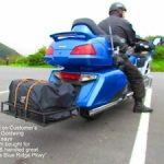
Has anyone tried removing The trunk from their SVTC? One of the things I really like about my victory cross country tour was the ease in which I could remove the trunk so I could go around town like a bagger. I really like the look of the eluder.
Link to comment
Share on other sites.

I had mine off for the purpose of installing a trailer hitch. I just looked and found that I didn't take a picture that would help you much. Here is what I have though.

Hey Spicer,, maybe get a peek at an Eluder shop manual and compare it to the SVTC shop manual to see how they each come apart and see if they mounting methods are different.. I got a hunch that Mom Yam used the same frame for both scoots and comparing notes may help in assessing the process.. Sounds fun and doable = all the best in coming up with something and would appreciate any thoughts/pictures of what you come up with!
- 2 weeks later...

GreenMtnHunter
Has anyone tried removing.... I really like the look of the eluder. Thanks
Agreed! Does the bike come from the crate with the trunk installed? If so, when mine arrives, I'd like to do the quick connects at that time....I'd have bought the Eluder but I need the reverse, and want the rear speaker option.
I've read that the bike comes with the trunk installed but with the rear bolts not installed or somethings so that the trunk tilts forward so to that the bike fits into a shorter crate. Not sure of the details.
Hi Freebird, been awhile, you are correct, my bike after the crate was removed

Thanks. I had read that somewhere but never seen a picture of it.
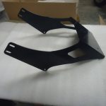
This thread is extremely interesting to me, and I am sure others as well. It is good to see the rear fender is not "deformed" to account for the trunk.
Did the bags need to be removed to get to the hardware to remove the trunk?
Did it look as though the wiring would tuck under the seat or would a "cover" need to be devised to tidy the wiring?
Was the seat cleanly finished on the back?
I wonder if performing a modification to the Eluder bracket for the backrest would suffice to allow for a "quicker" release function for the trunk?
Thanks so much for the pics!
This thread is extremely interesting to me, and I am sure others as well. It is good to see the rear fender is not "deformed" to account for the trunk. Did the bags need to be removed to get to the hardware to remove the trunk? Did it look as though the wiring would tuck under the seat or would a "cover" need to be devised to tidy the wiring? Was the seat cleanly finished on the back? I wonder if performing a modification to the Eluder bracket for the backrest would suffice to allow for a "quicker" release function for the trunk? Thanks so much for the pics!
The fender is not deformed, and the bracket itself is just a couple bolts. Mine was lowered and installed when I was away, but I do npt think the left saddlebag was removed for that operation...only four bolts and an electrical clip. The issue is that there are seven clips on the back rest and two wires, antenna, I believe that are not in clips. I should think you could hide them all in small bag behind the rear seat, and there may be just enough room to tuck them under it... I think it woild look pretty clean. My dealer laughed and said I was crazy...in a nice way....
- 3 years later...

Richard75013
I know this is an old topic but did anyone try this? I am very interested in this conversion? Cc @Spicermech @GreenMtnHunter @Freebird @PAVenture @cowpuc

16 hours ago, Richard75013 said: I know this is an old topic but did anyone try this? I am very interested in this conversion? Cc @Spicermech @GreenMtnHunter @Freebird @PAVenture @cowpuc
I just replied to you in another thread. See this
On 12/7/2022 at 11:04 AM, bpate4home said: I just replied to you in another thread. See this
I got it, thank you!!!!
Create an account or sign in to comment
You need to be a member in order to leave a comment
Create an account
Sign up for a new account in our community. It's easy!
Already have an account? Sign in here.
- Existing user? Sign In
- Unanswered Topics
- Online Users
- Leaderboard
- All Activity
- Subscriptions
- Create New...
- Victory Manuals
- Victory Cross Country Tour
Victory Victory Cross Country Tour Manuals

Victory Victory Cross Country Tour Service Manual (580 pages)
Table of contents, chapter 1 1 specifications / gauge / audio.
- Table of Contents 2
- General Information 4
- Service Rules 4
- Trademarks 4
- Safety Information 5
- 2012-2013 Cross Roads Classic™ / Hard-Ball 6
- 2012-2013 Cross Country ® / Cross Country Tour ® / Ness 8
- Gross Vehicle Weight Rating (Gvwr) 10
- Model Number Designation 11
- Vehicle Identification Number (Vin) Designation 11
- Vin Number / Manufacturer Label 11
- Veci / Neci / Tire Information Labels 12
- Engine Number Location 12
- Key Identification Number 12
- Saddlebag Warning Label 12
- Rear Shock Air Pressure Label 12
- Publications & Technical Literature 13
- Paint Colors by Model 13
- Paint Color Codes 14
- Break in Period 15
- Emissions 16
- Special Service Tools 17
- Transporting, Elevating, and Securing the Motorcycle 20
- Key Switch 21
- Speedometer 22
- Speedometer Gear Position Indicator 22
- Cross Roads Instrument Cluster 23
- Cross Country Instrument Cluster 24
- Multi Function Display - Cross Country (Mfd) 25
- Engine Error Codes (Cross Country) 25
- Clock (Cross Country) 26
- Trip Information (Cross Country) 26
- Gear Position (Cross Country) 26
- Trip Odometer (Cross Country) 26
- Temperature (Cross Country) 27
- Odometer (Cross Country) 27
- Changing Information Display Units (Cross Country) 27
- Hand Grip Heater Switch 27
- Seat Heater Switch (Cross Country Tour) 27
- Mode Button 28
- Hazard Switch (Emergency Flashers) 28
- Headlamp High / Low Beam Switch 28
- Turn Signal Switch 28
- Turn Signal Momentary Feature 29
- Starter Interlock 29
- Engine Stop Switch 29
- Engine Starter Button 29
- Front Brake Lever Reach Adjustment 29
- Audio / Com / Cruise Control Buttons 30
- Auxiliary Driving Light Switch (Cross Roads Classic) 30
- Radio / Audio System 30
- Cb Radio / Icom System 39
- Aux / Ipod 43
- XM Radio 45
- Sae Tap Drill Sizes 50
- Metric Tap Drill Sizes 50
- Fahrenheit to Celsius 51
- Measurement Conversion Chart 51
Maintenance Chapter 2 Maintenance 2
- Maintenance 53
- Service Specifications 53
- Maintenance Products 54
- Special Tools 54
- Chapter 2 55
- Periodic Maintenance 55
- Periodic Maintenance Interval Table 55
- Air Filter 56
- Engine Oil and Filter Change 59
- Engine Oil Level 59
- Reverse Idler Shaft Lubrication 60
- Idle Speed / Fast Idle Speed 61
- Tire Pressure / Inspection 61
- Cruise Control Cable 63
- Front Brake Lever Inspection / Lubrication 63
- Clutch Lever Lubrication 64
- Front Brake Lever Reach 64
- Clutch Lever Free Play 65
- Front Brake Fluid Level 66
- Rear Brake Fluid 66
- Brake Pad Inspection 67
- Foot Control Adjustment 68
- Rear Brake Pedal 68
- Shift Pedal 68
- Crankcase Ventilation System 69
- Evaporative Emission Control System (California Models) 69
- Fuel System Inspection 69
- Battery Charging / Storage / Inspection 71
- Battery Removal / Installation 72
- Cylinder Leakage Test 73
- Engine Compression Test 73
- Drive Belt Tension Gauge 74
- Drive Belt Wear Analysis 74
- Drive Belt Tension - Inspection 75
- Drive Belt Cleaning 76
- Sprocket Inspection 76
- Drive Belt Adjustment / Alignment 77
- Headlamp Aim Inspection 78
- Headlamp Aim Adjustment 79
- Sidestand Inspection 79
- Sidestand & Spring Removal 80
- Sidestand Pad Replacement 80
- Rear Suspension / Swingarm Inspection 81
- Rear Suspension Air Pressure Adjustment 82
- Front Fork / Suspension Inspection 83
- Fuse Replacement (Main Fuse Box) 84
- Fasteners 85
- Fuse Replacement (Remote Fuses) 85
- Cleaning 86
- Lock and Ignition Switch Lubrication 86
- Suede Finish Care 87
- Windshield Care 87
Frame-Body-Exhaust Chapter 3 Frame-Body-Exhaust
- 9924047 - 2012-2013 VICTORY Cross Roads / Cross Country Service Manual 89
- Chapter 3 Special Tools 90
- General Information 90
- Front Fender 91
- Ignition Switch / Iac Cover Removal / Installation 92
- Windshield (Cross Country) 93
- Windshield (Cross Country Tour) 94
- Windshield (Cross Roads) 95
- Headlamp Bezel 96
- Headlamp (Cross Country) 96
- Headlamp, Hid (Cross Country Tour) 97
- Headlamp Assembly View (Cross Country) 98
- Headlamp (Hid) Assembly View (Cross Country Tour) 98
- Hid Ballast (Cross Country Tour) 99
- Headlamp (Cross Roads) 99
- Headlamp Assembly View (Cross Roads) 100
- Auxiliary Driving Lights (Cross Roads) 101
- Speaker Grill 101
- Front Fairing - Upper (Cross Country) 101
- Dash Panel 102
- Fairing Mount Assembly View (Cross Country) 103
- Fairing Mount Removal 104
- Instrument Cluster / Speaker / Speaker Volume 105
- Fairing Trim / Front Turn Signal Assembly View 106
- Speedometer / Speedometer Mount (Cross Roads) 106
- Chin Fairing (Inner Grill) 107
- Chin Fairing (Outer and Rear) 107
- Highway Bars 108
- Front Fairing - Lower - (Cross Country Tour) 108
- Instrument Bezel (Cross Country) 110
- Side Cover Removal 111
- Saddlebag 112
- Antenna / Antenna Mount 112
- Saddlebag Assembly View 113
- Rear Fender / Saddlebag Mount 114
- Trunk Assembly View / Mount 116
- Tail Light / Turn Signal Assembly View 117
- Floorboard / Foot Control Mounting 118
- Passenger Footrest Mounting 119
- Passenger Floorboards (Adjustable) 120
- Assembly View - Exhaust Complete 122
- Assembly View - Muffler 123
- Assembly View - Head Pipes 124
Lubrication & Cooling Chapter 4 Lubrication & Cooling
- Chapter 4 127
- Oiling System 127
- Operation 127
- Special Tools 127
- Troubleshooting 127
- Specifications - Lubrication 128
- Diagram 129
- Assembly View - Oil Cooler and Lines 130
- Oil Cooler Inspection / Cleaning 131
- Oil Cooler / Oil Line Removal 131
- Oil Cooler / Oil Line Installation 131
- Lubrication Oil Pressure 132
- Cooling Oil Flow Inspection 132
- Oil Pump Removal 133
- Oil Pressure Relief Valves 134
- Oil Pump Inspection 135
- Oil Pump Disassembly 136
- Oil Pump Assembly 137
- Oil Pump Installation 139
Chapter 5 Fuel System / Fuel Injection
- Safety Precautions 144
- Special Tools 145
- Specifications 145
- Basics Troubleshooting 145
- Throttle Body Flow Screw and 145
- Idle Stop Screw 145
- Service Precautions 146
- Fuel Tank and Cap Mounting 147
- Fuel Tank Assembly View 148
- Fuel Tank Vent Water Drain Line Routing - 49 State 149
- Fuel Tank Evaporative Emissions System - California Models 150
- Fuel Pump / Level Sensor Reference Data 151
- Fuel Pump Assembly Views 152
- Air Intake / Box Frame Assembly View 153
- Idle Air Control Assembly View 154
- Fuel System Depressurization 155
- Priming the Fuel System 155
- Fuel Tank Vent Inspection - 49 State 155
- Fuel Tank Vent Inspection - California 156
- Fuel Tank Removal 156
- Fuel Tank Installation 157
- Fuel Pump Removal 159
- Fuel Filter Replacement 160
- Fuel Level Sensor Removal 161
- Fuel Level Sensor Installation 161
- Fuel Pump Installation 162
- Fuel Pump Circuit Diagram 164
- Fuel Pump Pressure Inspection 165
- Fuel Level Sensor Resistance Test 166
- Fuel Level Sensor Bypass Test 166
- Fuel Pump Electrical Diagnostics 167
- Fuel Pump Supply Voltage Test 167
- Fuel Pump Current Draw Test 169
- Idle Air Control Removal 170
- Throttle Body Removal 171
- Throttle Body Installation 172
- Fuel Injection Component Locations 173
- Fuel Rail / Fuel Injector Removal 174
- Fuel Rail Installation 174
- Fuel Injection System - Overview of Operation 175
- Idle Air Control (Iac) - Overview of Operation 175
- Self-Diagnostic Feature 175
- Ecm Connector Map 176
- Viewing and Clearing Trouble Codes 177
- Trouble Codes 177
- Throttle Position Sensor (Tps) Diagnostics 183
- Tmap Diagnostics 184
- Air Temperature Sensor (Ats) Diagnostics 185
- Cylinder Head Temperature Sensor (Cht) Diagnostics 186
- Idle Air Control (Iac) 187
- Vehicle Speed Sensor Test 188
- Neutral Indicator Switch Test 188
- Memory Check Sum Error 188
- Tipover Sensor 188
- Crankshaft Position Sensor Diagnostics 189
- Battery Voltage at Ecm Diagnostics 189
- Reprogramming Process 195
- Troubleshooting 199
Engine Removal & Installation Chapter 6 Engine Removal & Installation
- Chapter 6 205
- General 205
- Overview - Engine Removal 205
- Specifications 205
- Special Tools 206
- Engine Mounting - Airbox / Main Frame Assembly 207
- Preparation for Removal 208
- Precautions 208
- Removal Procedure 208
- Injector Removal 214
- Preparation for Installation 215
- Engine Attachments & Notes 218
Cylinder Head & Valve Train Chapter 7 Cylinder Head & Valve Train
- Chapter 7 223
- General Information 223
- Important Notes 223
- Special Tools 223
- Specifications 224
- Cam Drive & Valve Cover 225
- Camshaft Carrier / Rocker Arm 226
- Cylinder Head 227
- Camshaft Timing Quick Reference 228
- Camshaft Drive Cover 229
- Valve Cover Removal 229
- Valve Cover Installation 229
- Cam Chain Tensioner Removal 229
- Cam Chain Tensioner Inspection 230
- Cam Chain Tensioner Installation 230
- Camshaft Chain & Sprocket Removal 231
- Camshaft Carrier Removal 232
- Rocker Arm & Shaft Inspection 232
- Camshaft Inspection 233
- Cylinder Head Removal 233
- Cylinder Head Disassembly 234
- Cylinder Head Inspection 235
- Valve Spring Free Length Inspection 235
- Valve Inspection 237
- Valve Guide Removal / Installation 238
- Valve Seat Inspection 239
- Valve Seat Reconditioning 239
- Cylinder Head Assembly 240
- Cylinder Head / Camshaft Installation 242
- Camshaft Timing - Rear Cylinder 244
- Camshaft Chain Guide Installation 244
- Camshaft Timing - Front Cylinder 245
- Troubleshooting, Cylinder Head and Valve Train 248
Cylinder & Piston Chapter 8 Cylinder & Piston
- Base Gasket Sealing & Cylinder Stud Torque 253
- Chapter 8 253
- Cylinder & Piston 253
- General 253
- Piston Ring Profile and Orientation 253
- Special Tools 254
- Specifications 254
- Cylinder Bore Measurement 255
- Cylinder Inspection 255
- Cylinder Removal 255
- Piston to Cylinder Clearance Worksheet 256
- Cylinder Warpage Measurement 257
- Piston & Piston Ring Inspection 257
- Piston & Piston Ring Removal 257
- Piston Pin / Pin Bore Inspection 258
- Cylinder Stud Replacement 259
- Piston Ring Installation 259
- Piston Installation 260
- Cylinder Installation 261
- Troubleshooting, Cylinder & Piston 262
Clutch, Primary, & Shift Linkage Chapter 9 Clutch, Primary, & Shift Linkage
- General 265
- Special Tools 265
- Specifications 265
- Assembly Views & Torque Values 266
- Chapter 9 266
- Shift Linkage / Footrest - Fastener Torque 267
- Primary Cover 268
- Shift Mechanism 269
- Clutch Pinion Shaft Removal 270
- Clutch Pinion Shaft Bearing Inspection 270
- Clutch Pinion Shaft Seal Removal & Installation 271
- Clutch Pinion Shaft Installation 271
- Primary Cover Removal 272
- Shift Ratchet Removal & Inspection 273
- Shift Ratchet Installation 274
- Shift Shaft Bearing & Seal Replacement 274
- Primary Cover Installation 275
- Locking the Crankshaft 275
- Clutch Assembly View & Torque 276
- Clutch Removal 277
- Clutch Disassembly 278
- Clutch Assembly 281
- Clutch Installation 283
- Primary Drive Assembly View & Torque 284
- Torque Compensator Removal 285
- Torque Compensator Inspection (Early Build) 285
- Torque Compensator Inspection (Late Build) 286
- Torque Compensator Installation 286
- Rotor (Flywheel) Removal 287
- Rotor (Flywheel) Installation 288
- Split Gear Removal 288
- Split Gear Inspection 289
- Split Gear Installation 289
- Starter Clutch Removal / Inspection 291
- Primary Drive Gear Removal / Inspection 291
- Starter Torque Limit Clutch Inspection 292
- Primary Drive Gear Installation 292
- Starter Gear / Starter Clutch Installation 293
- Troubleshooting 294
Transmission & Crankshaft Chapter 10 Transmission & Crankshaft
- Chapter 10 301
- Crankcase Separation 301
- Service Procedures 301
- Power Delivery (Typical 6-Speed) 305
- Nsa (Neutral Selection Assist) Transmission Information 306
- Transmission Removal 308
- Clutch Shaft Inspection / Removal 309
- Transmission Inspection 309
- Connecting Rod Removal / Identification 311
- Connecting Rod Side Clearance Inspection 311
- Connecting Rod Inspection (Big End) 312
- Connecting Rod Bearing Clearance Inspection (Typical) 313
- Connecting Rod Bearing Inspection 313
- Connecting Rod Bearing Selection 314
- Connecting Rod Installation 315
- Crankshaft Inspection 315
- Main Bearing Inspection 316
- Main Bearing Oil Clearance Inspection 316
- Left Crankcase Assembly 317
- Crankcase Reed Valve Assembly Removal & Inspection 318
- Crankshaft Installation 318
- Right Crankcase Assembly 318
- Balance Shaft Removal & Inspection 319
- Balance Shaft Installation 320
- Transmission Installation 319
- Crankcase Assembly & Sealing 321
- Stake Nut Installation 324
- Troubleshooting 325
Drive Line / Reverse System Chapter 11 Drive Line / Reverse System
- Assembly Views & Torque Values 329
- Chapter 11 329
- Drive Line / Reverse System 329
- Rear Wheel Fastener Torques 329
- Special Tools 329
- Drive Sprocket Fastener Torques 330
- Belt Specifications / Belt Guard 331
- Belt Inspection 332
- Belt Installation 332
- Drive Sprocket and Seal Removal 332
- Drive Sprocket Inspection 333
- Drive Sprocket and Seal Installation 333
- Rear Sprocket Removal 335
- Rear Sprocket Inspection 335
- Rear Sprocket Installation 335
- Reverse Drive Mechanism (if Equipped) 336
- Reverse Gear Case Assembly View 337
- Reverse Linkage Adjustment 338
- Reverse System Test 339
- Reverse System Fuse Location 339
- Reverse Coupler Shaft Key Replacement 340
- Troubleshooting 341
Chapter 12 Front Suspension / Controls
- Front Suspension / Controls 343
- General 343
- Maintenance Products 343
- Special Tools 343
- Torque Specifications 343
- Fork Specifications 344
- Clutch Cable / Lever Perch 349
- Front Fork Attachments 350
- Front Axle Assembly View 351
- Fork Tube Installation Steps 352
- Steering Head Adjustment / Top Triple Clamp 353
- Fork Tube Assembly View 354
- Assembly View, Cast Front Wheel 355
- Assembly View, Billet Front Wheel 356
- Assembly View, Spoked Front Wheel 357
- Heated Grips 358
- Handlebar Removal 359
- Handlebar Adjustment - Hard-Ball 362
- Handlebar Installation 363
- Clutch Cable 364
- Throttle Cable 365
- Front Wheel Removal 367
- Front Axle Inspection 368
- Front Wheel Inspection 368
- Brake Disc Removal 368
- Brake Disc Installation 369
- Front Wheel Bearing Inspection 369
- Front Wheel Bearing Removal 370
- Front Wheel Bearing Installation 370
- Front Fork Removal 371
- Front Fork Tube Installation 372
- Front Fork Disassembly 373
- Fork Seal Removal / Tube Disassembly 375
- Front Fork Inspection 376
- Front Fork Tube Assembly 377
- Fork Oil Filling / Level Setting 379
- Triple Clamp Removal 382
- Steering Head Bearing Inspection 384
- Triple Clamp Installation 384
- Steering Head Bearing Replacement 386
- Steering Head Bearing Adjustment 388
- Troubleshooting 389
Rear Wheel & Suspension Chapter 13 Rear Wheel & Suspension
- General Information 393
- Rear Wheel & Suspension 393
- Specifications 394
- Assembly View - Rear Axle & Adjusters 395
- Assembly Views & Torque 395
- Chapter 13 395
- Assembly View - Swingarm & Suspension 396
- Assembly View, Cast Rear Wheel 397
- Assembly View, Billet Rear Wheel 398
- Assembly View, Spoked Rear Wheel 399
- Rear Wheel Removal 400
- Rear Axle Inspection 401
- Rear Wheel Inspection 401
- Rear Wheel Bearing Inspection 402
- Wheel Bearing Removal (Typical) 402
- Wheel Bearing Installation (Typical) 404
- Brake Disc Removal 406
- Brake Disc Installation 406
- Rear Sprocket Removal 406
- Rear Sprocket Installation 407
- Rear Wheel Installation 407
- Rear Shock Service Data 410
- Rear Shock Removal 411
- Rear Shock and Rocker Inspection 413
- Shock Absorber Installation 414
- Swing Arm Removal 416
- Swing Arm Bushings / Bearing Replacement 418
- Swing Arm Installation 419
- Troubleshooting 420
Tires / Wheels Chapter 14 Tires / Wheels
- Chapter 14 Warnings / Precautions 423
- General / Safety 423
- Special Tools 424
- Tire Pressure / Loading 424
- Wheel Specifications 424
- Tire Wear Patterns & General Causes 425
- Front Tire Cupping 425
- Tire Changing 426
- Tire Removal 427
- Visual Inspection & Runout 428
- Tire Repair Precautions 429
- Tire Valve and Stem Inspection 429
- Valve Stem Installation - Rubber 429
- Valve Stem Installation - Metal 429
- Tire Installation 430
- Tire Balancing 432
- Spoked Wheel Offset Adjustment 435
- Wheel Truing 435
- Final Tightening 436
- Wheel Lacing 436
- Spoke Maintenance 438
- Troubleshooting 439
Brakes Chapter 15 Brakes
- Brake System Safety 441
- Specifications 442
- Torque Specifications 442
- Abs General Information 443
- Abs System Safety Precautions 443
- Anti-Lock Brake System (Abs) 443
- Chapter 15 443
- Special Tools 443
- Abs Overview of Operation 444
- Abs System Components 444
- Front Brake (Abs) 445
- Rear Brake (Abs) 446
- Master Cylinders / Assembly View 447
- Abs Module / Assembly View 448
- Wheel Speed Sensor - Front 449
- Wheel Speed Sensor - Rear 450
- Front Brake Calipers 451
- Rear Brake Caliper 452
- Abs System Circuit Diagram 453
- Wheel Speed Sensor Service 454
- Wheel Speed Sensor Airgap Adjustment (Front & Rear) 454
- Abs Module Service 455
- Brake Fluid Replacement & Bleeding Precautions 456
- Abs Brake Vacuum Bleeder 457
- Abs Fluid Change 457
- Abs Rear Brake Bleeding 457
- Abs Front Brake System Bleeding 458
- Brake Lever Reserve Inspection 459
- Front Brake Pad Replacement 460
- Rear Brake Pad Replacement 462
- Brake Disc Inspection (Front & Rear) 464
- Front Master Cylinder Service 464
- Front Master Cylinder Installation 467
- Front Caliper Service 468
- Front Caliper Service (Cont) 469
- Front Caliper Installation 470
- Rear Master Cylinder Service 471
- Rear Master Cylinder Installation 474
- Rear Caliper Service 474
- Rear Caliper Installation 476
- Abs Trouble Codes 477
- Brake System Troubleshooting 478
- Abs System Troubleshooting 480
Battery Charging System Chapter 16 Battery Charging System
- Battery Charging System 483
- Chapter 16 483
- Charging System & Alternator 483
- General 483
- Specifications 483
- Fastener Torque Reference 484
- General 486
- Battery Charging - New Battery 488
- Battery Charging - General 488
- Troubleshooting 489
- Battery Load Test 490
- Current Draw Inspection (Key Off) 490
- Regulated Voltage / Amperage Output Inspection 491
- Stator No-Load Ac Voltage Output Inspection 492
- Stator Resistance Inspection 493
- Stator Windings to Ground Inspection 493
- Voltage Drop: Rectifier / Regulator to Battery(+) 494
- Rectifier / Regulator Connector Inspection 494
- Diode Leakage Test 495
- Regulator / Rectifier Test 496
- Rectifier / Regulator Replacement 497
Ignition Chapter 17 Ignition
- Chapter 17 Ignition System Specifications 501
- Troubleshooting 502
- Ignition Circuit Diagram 503
- Ecm Connector Map 504
- Test Lead Adapter Kit 504
- Ignition System Test Flowchart 505
- Battery Voltage Inspection - Test 1 506
- Spark Inspection - Test 2 506
- Coil High Tension Leads - Test 3 507
- Ignition Coil Signal - Test 4 507
- Ignition Coil Resistance - Test 5 508
- Crankshaft Position Sensor (Cps) Resistance Inspection - Test 509
- Crank Position Sensor Circuit and Signal Test 6A 510
- Crank Position Sensor Circuit Continuity Test 6B 510
- Ground Circuit Inspection - Test 7 510
- Ignition Coil Installation 511
- Ignition Coil Removal 511
- Ignition Switch Removal 511
Electric Starter Chapter 18 Electric Starter
- Chapter 18 Fastener Torque Specifications 513
- General 513
- Specifications 513
- Troubleshooting Flow Chart Menu 514
- Starter Circuit Diagram 515
- Battery Inspection & Charging Procedures 518
- Battery Load Test 518
- Starter Relay Ground Bypass Circuit Test 518
- Neutral Switch Bypass Test 519
- Clutch Switch / Circuit Test 520
- Clutch Switch Removal 521
- Clutch Switch Installation 521
- Starter Relay to Starter Motor Positive Cable Bypass Test 521
- Starter Relay Positive Circuit Test 522
- Starter Relay Bypass Test 522
- Starter Relay to Starter Motor Positive Cable Bypass Test 523
- Positive Side Voltage Drop Test 524
- Negative Cable Bypass Test 526
- Negative Side Voltage Drop Test 527
- Starter Current Draw Test 529
- Starter Motor Removal 530
- Starter Motor Installation 530
- Starter Clutch Removal 530
Wiring / Lighting Systems Chapter 19 Wiring / Lighting Systems
- Headlamp 533
- Chapter 19 534
- Headlamp Assembly View - Cross Country 534
- Headlamp (Hid) - Cross Country Tour 535
- Headlamp System Wiring 536
- Tail Lamp / Brake Lamp System Wiring Diagram 537
- Turn Signal System Wiring Diagram 538
- Turn Signal Flasher Module - Input / Output 539
- Turn Signal System Overview and Diagnostics 540
- Speed Sensor Test 541
- Tachometer Signal Test 542
- Speedometer Gear Position Indicator 542
- Rear Brake Light Switch Test 543
- Front Brake Light Switch Test 543
- Neutral Indicator Switch Inspection 544
- Neutral Indicator Switch Removal 544
- Clutch Switch Testing 544
- Tipover Sensor (Angle Sensor) 545
- Side Stand Switch Information (Eu Models Only) 546
- Side Stand Switch Testing 546
- System Diagram 547
- Heated Seat / Hand Grip Wiring Diagram 549
- Heated Grips 550
- Ground Locations 552
- Connector Pin Inspection 552
- Operation Overview - Setting Speed 553
- Operation Overview 553
- Cruise Control Diagnostics 554
- Cruise Module Input / Output 555
- Reverse System Diagnostics 557
- Reverse System Safety 559
- Operating the Reverse System 559
- Reverse Module / Fuse Access 559
Advertisement

Victory Victory Cross Country Tour Owner's Manual (130 pages)
- Table of Contents 7
- Introduction 8
- Safe Riding Practices 10
- Transporting the Motorcycle 16
- Electromagnetic Interference 17
- Reporting Safety Defects 19
- Ignition Key Number 20
- Engine Identification Number 20
- Left Side View 21
- Right Side View 21
- Top View 22
- Ignition Switch 23
- Indicator Lamps 29
- Left Handlebar Switches 33
- Mode Button 33
- Right Handlebar Switches 34
- Clutch Lever 35
- Gear Shift Pedal 35
- Pedal Adjustment 37
- Tilt Sensor 38
- Fuel Cap 39
- Tool Kit 39
- Engine Oil Level 42
- Fuel Level 42
- Front Brake Lever 43
- Rear Brake Pedal 44
- Brake Pads 45
- Front Suspension 46
- Rear Suspension 46
- Engine Break-In 48
- Starting the Engine 50
- Shifting Gears 51
- Parking on a Slope 55
- Stopping the Engine 55
- Break-In Maintenance 58
- Major Maintenance 58
- Periodic Maintenance 58
- Maintenance Log 60
- Air Filter 62
- Fuel Tank Removal 62
- Drive Belt Condition 66
- Rear Suspension Adjustment 70
- Swing Arm / Rear Axle Inspection 71
- Steering Head Inspection 72
- Fast Idle 73
- Throttle Cable Freeplay 74
- Throttle Control Inspection 74
- Throttle Cable Lubrication 75
- Rear Brake Fluid 77
- Front Brake Fluid 78
- Wheel Inspection 79
- Tire Pressure 80
- Tire Tread Depth 80
- Battery Removal 81
- Battery Installation 82
- Sidestand Lubrication 82
- Handlebar Position 83
- Side Covers 84
- Saddlebag Bumpers 85
- Headlight Aim Inspection 86
- Fuse Replacement 88
- Electrical Precautions 89
- Exhaust System Inspection 89
- Elevating the Motorcycle 90
- Fastener Inspection 90
- Troubleshooting 91
- Victory Cleaning Products 93
- Leather, Rubber and Vinyl Care 97
- Clean and Protect the Motorcycle 98
- Tire Inflation 98
- Battery Care 99
- Park and Cover the Motorcycle 99
- Removal from Storage 100
- Emissions Control System Warranty 102
- Victory Motorcycle Warranty Policy 104
- Engine Oil Recommendation 107
- Fuel Recommendation 107
- Identification Number Record 107
- System Overview 108
- System Operation 110
- CB Radio / Intercom (ICOM) 117
- Getting Started 117
- Push-To-Talk (Ptt) 118
- Headset Receptacles 120
- AUX / Ipod 121
- Ipod Song Control 121
- Ipod Playlists 122
- XM Ready Subscription 123
- XM Ready Legal 123
- XM Radio Menu Options 124
- XM Radio Reception 124
- XM Radio Categories 125
- XM Radio Channels 125
- Nav Mp3 126
- Battery 127
Related Products
- Victory Victory Cross Country
- Victory Victory Cross Roads Limited Edition
- Victory Victory Cross Roads
- Victory Cross Roads Classic
- Victory THE Countess
- Victory CBR60HC-1
- Victory CBR72HC-1
- Victory CBR84HC-1
- Victory CBR112HC-1
- Victory CLASSIC
Victory Categories
Upload manual
- Luggage and Saddlebags
Cross Country Xc Custom Luggage and Victory Cross Country Accessories and Victory Cross Country Parts
Showing 1–33 of 38 results

3510-0039 3510-0039 Cruis’n™ Tool Roll Bag – Fork Mount
Cross Country / Cross Roads / Hard Ball Tour Pack / Trunk mount kit
VICTORY TRAILER HITCH COOLER RACK

BR1800 TACTICAL SISSY BAR BAG BLACKED OUT ZIPPERS WITH BACKREST PAD

BR3400 TACTICAL SISSY BAR BAG BLACKED OUT ZIPPERS WITH BACKREST PAD
![SISSY BAR BAG BR3400 [3515-0107]](https://www.victoryonly.com/wp-content/uploads/35150107-6-150x150.png "victory cross country tour trunk removal")
BR3400 BACK SEAT OR SISSY BAR BAG WITH BACKREST PAD

HMD-178 Cross Country Speaker Lid Savers Tethers

Momentum Drifter Bag 18.5″ wide x 12″ deep x 11.5″ tall

TAIL BAG WEEKENDER BAG 3502-0317

3516-0269 ROUTE 1 TRAVELER TOUR TRUNK BAG

5284 BAG MOMENTUM ROAD WARRIOR 19 x 12 x 16

5287 Saddlebag Organizer Set

Victory Cross Country, Cross Roads, Victory Cross Trunk Luggage

Victory Cross Country, Cross Roads, Victory Skull Trunk Luggage

VICTORY CROSS COUNTRY TRIBAL DESIGN REAR BACK REST LUGGAGE RACK

VICTORY CROSS COUNTRY CROSS DESIGN REAR BACK REST LUGGAGE RACK

VICTORY CROSS VICTORY LUGGAGE RACK TRIBAL

VICTORY CROSS COUNTRY LUGGAGE RACK SKULL

VICTORY CROSS VICTORY LUGGAGE RACK

91-314a Quick Release Saddlebag Fasteners Cross Bags

5288 Motorcycle Pet Carrier Grand Pet Palace

Victory Cross Country Rack for Trunk Tribal

Passenger Rider Backrest Organizer

Windshield Center Accent For Victory Cross Country & Tour

BR4100 BACKREST COOLER BAG FOR LUGGAGE RACK OR SISSYBAR

SOLO RACK BAG

Bag SPORT TRUNK AND RACK BAG

XR1.0 Roll Bag Kuryakyn

Trunkbox Corbin Victory Cross Roads and Cross Country
UNIVERSAL SADDLEBAG HARD MOUNT KIT

3510-0038 Cruis’n™ Tool Bag VICTORY MOTORCYCLE

CRUIS’N DELUXE TOOL BAG FOR VICTORY MOTORCYCLE
Victory shop.
- Cargo Trailers
- Accessory Mounts
- Engine and Wedge Covers
- Fairings and Bodies
- General Accessories
- Gerbing Heated Clothing
- Gift & Specialty
- Handlebars and Controls
- Highway Bars
- Hitch Trailer
- Lowering Link
- Maintenance
- Mirror and Mirror Arms
- Navigation & Camera
- Oil Dipstick
- Pegs, Grips, & Floorboards
- Performance
- Seats and Pads
- Sissybars, Backrests, and Racks
- Wheels and Accessories
- Windshields
- Cross Roads
- DECALS AND AUTOMOTIVE
- Fuel Pump and System
- Gerbing Heated Clothing Line
- New Arrivals
- Spark Plugs
- Starter & Starter Drive
- Touring Cruiser
- Uncategorized

- Forum Listing
- Marketplace
- Advanced Search
- Victory Forum
- Victory Cross Country
Removing battery....

- Add to quote
Gday all, while I was playing round with some electrical stuff the other day, I thought that while the front cover was off, I would remove the battery and clean up that little containing area as well. Here is my question.... I can't seem to get a good enough grip on the battery to be able to lift it up over the front lip of the tray that holds it, is there a knack to this that I need to know..... Anyway, The battery is still there with all the road grime on it..... I might add that to get at the battery, I do not have a bike lift to raise the whole thing to chest level or there abouts which I would imagine makes it easier to get at things.... I have a jack is all and I still have to lay on the floor to get level with this sort of stuff and it is very awkward to do things while one is on ones back or side.....

For the first removal i had to pry it up with a flat screw driver. Its in there pretty snug at first but once you get it out its much easier the second and by the third you can pretty much pick it up with just one hand

I may be wrong on this but I read somewhere long ago that the battery also has double sided tape on it as well, so the first time removing it is very difficult. Of course this could be wrong, or it could only be on certain models. Let us know.

There's no tape holding it. It's just wedged it the tight with all the crud build up. I had to work mine out with a flat screwdriver the first time. Just take your time it will come out.

It helps to put a big plastic zip tie thru each hole Iin the battery post. Helps lifting it
That's a great idea.
Thanks to all for the replies and tips... This bloody new vog forum software says I am still watching and even have the email me box ticked and yet none of these replies are alerting me and that is why I have not thanked any of you for your prompt replies.... Gramps....

When you do a battery change or remove one for maintenance, have a close look at the left side screw for the plastic grill panel and the underside of the battery. The screw is the one that sits underneath the grill on the LHS. I found that my stock screw was a touch too long and had driven through the foam rubber packing on the bottom of the battery bay. It had come close to punching a hole through the bottom of the old battery. It wasn't readily visible from the top with the battery out as the foam closes over the hole. I picked up the battery and felt the hole that was forming with my finger, so I flipped it over to have a look. The new battery went back in with extra washers on the left-side screw to stop the same from happening. I've since replaced all the small screws with better stainless ones. The right-side screw is clear of the battery as it protrudes into what I presume would be the ABS module bay (like my old BMW bikes under the tank), so only the left one directly under the battery is the problem.

The battery box has a couple of holes in the bottom, push battery up with your fingers and lift out.
Mike - I'd have needed a jack under my fingers to lift mine out that way. The battery was a replacement from the previous owner that had failed, and was a really snug fit, held even tighter with a lot of solidified crud from wet roads and muddy roadworks. I just did the old rock back and forward until it came loose, and then slipped my home-made pry bar underneath and pried it loose. That tool is simply an old screwdriver with a flat blade and some heat-shrink over the blade-end to protect whatever it is I am lifting/splitting. It gets a lot of use, and doesn't scratch things up.

While you're in there... you should do the 40 amp Breaker upgrade. 40A circuit breaker upgrade. . . .DONE | Victory Motorcycles: Motorcycle Forums
- ?
- 49.6K members
Top Contributors this Month


- Forum Listing
- Marketplace
- Advanced Search
- Victory Motorcycles
- Victory Cross Country and Cross Roads
XC trunk wiring

- Add to quote
I have a 2014 XC and recently purchased a trunk from a 2014 XCT. Before I purchased it I located the plug under the left side panel of my bike so all was well. I have received the trunk and I find that #1 the shells on both the plugs are exactly the same size so they won't mate up and #2 the plug on the bike side has 4 wires going into it and the trunk side has 8 coming out. Obviously I'm missing something (physically and mentally!). I have searched the other XC threads on trunks and have not found anything like this. Can anyone help?

My CCT came with the trunk and wiring standard...if it would help I can go outside and take a pic of what the connection looks like. Skin
Never mind. After reading a few more posts and actually seeing the plug I was looking at the wrong one. There is one that is actually plugged into a blanking port that has the same type connector, which is the one I was looking at, and then there is the correct one that was tucked up under the seat. All is well, the tail light works and I'm rocking and rolling. Thanks for your help though.
Glad you got it handled. Safe riding. Skin

I was thinking as I read this. I thought it plugged in under the seat area. Never have taken it off so..... They say quick release but, depends on who is doing it I guess. Plus where do I put it, and then I got no place to put my lid when I go in for ice cream.
- ?
- 497.8K posts
- 48.7K members
Top Contributors this Month

IMAGES
VIDEO
COMMENTS
How to remove the trunk from the 2013 cross country tour.1. Take off Saddle bags2. Loosen bolts3. Undo locks4. Remove
Recently got a 2012 XC Tour. Decided to remove the trunk just because. ... 2012 Victory Cross Country Tour (Stage 1) 2011 Victory Cross Country (traded in on XCT) 2009 Triumph Rocket III Touring (traded in on XC) 1998 Valkyrie Tourer (Hydralocked - sold as is) 1966 Honda 305 Dream (for sale)
I have been trying to understand what exactly is involved in removing the trunk on the XC Tour All I can find is the video below. Is this coorect? Two latches and the electrical plug? The reason I ask is becasue I thought I read somewhere that their are two additional bolts that have to be removed, so I just wanted some clarification.
2014 Cross Country Tour - Black - Watch my Victory videos here 2012 Triumph Bonneville - Black (Sold - Feb 2017) ... Bill P. (2012 XCT, Sold in 2017), Gallery: 2012 Victory Cross Country Tour. ... I found it more difficult to remove/re-install the right side, so I remove front floor board bolt and loosen the rear to let the floor board hang. ...
One of the things I really like about my victory cross country tour was the ease in which I could remove the trunk so I could go around town like a bagger. I really like the look of the eluder. ... One of the things I really like about my victory cross country tour was the ease in which I could remove the trunk so I could go around town like a ...
2013 Victory Cross Country Tour - Boardwalk Blue 2010 Kawasaki Vulcan 1700 Nomad - Metallic Diablo Black / Metallic Titanium ... Never tried to remove my tour pack, been way to hot! Sorry guys. Will give it a shot and see how she looks. ... 2014 Tequila Gold -w- Flames Cross Country. 16" Jurock Windshield, Color-matched trunk, and Victory Tri ...
Victory Victory Cross Country Tour Pdf User Manuals. View online or download Victory Victory Cross Country Tour Owner's Manual ... Trunk Assembly View / Mount. 116. Tail Light / Turn Signal Assembly View. 117. Floorboard / Foot Control Mounting. 118. Passenger Footrest Mounting. 119. ... Engine Removal & Installation Chapter 6 Engine Removal ...
Trunk removed. ness honkers lloydz air box, bag rails Rich's custom gel/ ostrich seat .Bag locks. chrome pass boards. Ignition relocate.Kury mirrors, There's a plug at the end of a cable that runs from the rear of your seat towards the middle of it, along the left (port) side.
Victory Motorcycles. Victory Cross Country and Cross Roads. Trunk removal. 2615 Views ...
Victory Cross Country Tour Trunk Liner Kit Installation Instructional Videowww.saddlebaglinerkit.com
4. Remove passenger backrest pad (Pic 4) 5. Remove speakers grilles 6. Remove speakers (Pic 5) 7. Remove speaker housings (Pic 6 & 7) 8. Unplug the 2-pin power connector on the new harness and set the piece with the fuse aside at this time. 9. From the inside-left of the trunk, thread the left side speaker wires, blue trigger wire and power ...
Add the foolproof top trunk and front compartments, and the Cross Country Tour yields 41.1 gallons of space. During my touring trip, I had enough room to pack an extra lid for some open-face ...
I created this video with the YouTube Video Editor (http://www.youtube.com/editor)
Victory Forum. Victory Cross Country. Trunk Removal on CCT. Jump to Latest Follow 21 - 24 of 24 Posts. 1 2. X. X Ring · Registered. Joined Jun 26, 2015 · 82 Posts ...
Off a 2013 Cross Country - Body of trunk is in good solid shape - No key - See video below on how to make your current key work. ... Sunset Red - Off a 2013 Cross Country; Lock & Ride Tour Pack; No key - see video below on how to make your current key work. ... Victory Cross Country Front Brake Master Cylinder, Lever & Mirror ASM Our Price ...
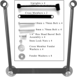
IndyVictory. 4079 posts · Joined 2018. #2 · Nov 21, 2021. You would need the tube things that the trunk snaps onto. Read old posts on using PVC pipe for that. Not sure if crossroads has the connector for the trunk wiring. Sunset Red 2012 Cross Country Tour. Purchased May 2018. Polk 652 front, 522 trunk, Nautilus air horn, 17" rubber antenna ...
Witchdoctors.com shows how to install a set of Alpine speakers into a Victory Cross Country / Tour trunk. Witchdoctors offers a variety of aftermarket motorc...
263 posts · Joined 2011. #6 · Sep 22, 2012. The install of the rear speakers is a piece of cake. There's three large screws holding on the lower part of the passenger backrest pad from inside the trunk (6mm two at the top and one at the bottom). Then there's one screw on each grill holding it once you get the pad off.
Victory Cross Country, Cross Roads, Victory Skull Trunk Luggage $ 249.99; VICTORY CROSS COUNTRY TRIBAL DESIGN REAR BACK REST LUGGAGE RACK ... Windshield Center Accent For Victory Cross Country & Tour $ 39.99; Sale! BR4100 BACKREST COOLER BAG FOR LUGGAGE RACK OR SISSYBAR $ 209.95 $ 199.95; Sale! SOLO RACK BAG $ 54.99 $ 49.95; SOLO RACK BAG $ 109.95;
Couldn't find this anywhere online so here is the quick method to remove the side fairing covers from a 2014 Cross Country Tour. These are bolted to the engi...
2014 Cross Country Tour - Black - Watch my Victory videos here 2012 Triumph Bonneville - Black (Sold - Feb 2017) ... Long horn highway pegs, brake light flasher on trunk brake lights, Dains brake pedal, Brass shifter bushings, Hi flow air filter, adjustable timing wheel, PC5 fuel controller, Dyno Tune by The Vic Shop, trunk lid rack and saddle ...
XC trunk wiring. I have a 2014 XC and recently purchased a trunk from a 2014 XCT. Before I purchased it I located the plug under the left side panel of my bike so all was well. I have received the trunk and I find that #1 the shells on both the plugs are exactly the same size so they won't mate up and #2 the plug on the bike side has 4 wires ...
https://www.vicbaggers.com/product-page/victory-cross-country-magnum-tour-pack-complete-kit