
Substation Design | Power System Analysis

Power Circuit Breaker – Operation and Control Scheme
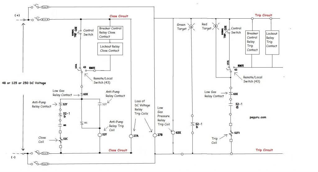
Understanding the breaker scheme is important if you plan on designing a substation. Quite often, it is overwhelming to make sense of the entire scheme at a glance. Therefore, the figure below depicting a circuit breaker scheme will be used to simplify and explain various elements of the breaker’s design and its control.
Forms of Contact
Before explaining what each device in the scheme does, understanding the different forms of auxiliary contact is necessary. Every breaker comes fitted with an auxiliary switch. It is mechanically linked to the breaker’s trip-close mechanism. Within the auxiliary switch case you can have either form ‘ a ‘ contact (a.k.a. 52a per ANSI) or form ‘ b ‘ (a.k.a. 52b).
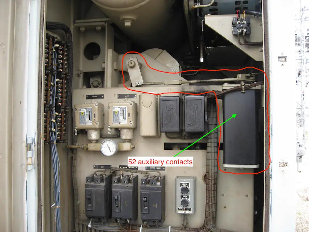
A form ‘ a ‘ contact represents a Normally Open (N.O.) contact. Thus when the breaker is open, its 52a contacts are open. When the breaker is closed, the 52a contacts are closed. The 52a contact follows the status of the breaker .
A form ‘ b ‘ contact represents a Normally Closed (N.C.) contact. It operates exactly opposite of what an ‘a’ does . When the breaker is open, the 52b contacts are closed. When the breaker is closed, the 52b contacts are open.
With the 52a contact in the trip circuit (as shown in the scheme above), once the breaker opens, this contact opens too. Now no matter what the relays do, the trip coil is isolated. On the flip side, with the breaker open, the 52b contact in the close circuit is closed – allowing the close operation when desired.
Apart from breaker auxiliary switch contacts, you will see relays such as anti-pump relay 52Y, low gas relay 63X, under voltage relay 27, etc in the breaker scheme. The ‘a’ and ‘b’ contacts from each of these relays are interlocked with other relays or switches such that they either permit or not permit the breaker operation.
Circuit Breaker Trip Scheme
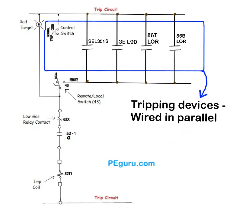
For the trip circuit, you must wire the tripping relays’ ‘a’ contact in parallel. See Figure 2 . Therefore when any one relay or switch contact closes, thus completing the circuit, the breaker trips. The only exception to the parallel wiring of contacts is the low-gas auxiliary relay contact (63X in the figure). This one is wired in series. Why?
Modern power circuit breakers employ Sulfur Hexa-Flouride (SF6) gas to extinguish an arc. Without adequate gas i.e. reduced interrupting capability, a flash-over can occur inside the tank. To prevent flash-overs due to low gas, breakers are fitted with ANSI ’63’ relay. Tripping of breaker is cut out by this relay’s contact.
Most modern circuit breakers are specified with two trip coils. Energizing either one trips the breaker. Since a good amount of redundancy is built into the protection and control of a power system, it is not uncommon to see all primary relaying in the system tripping trip coil 1 and the back-up tripping trip coil 2.
At this point, I hope the reader has grasped the strategy of series-parallel placement of relay contacts.
Let’s look at other relays and switches from the trip circuit of our breaker. The 27B under-voltage relay trip coil is connected across the same DC source as the one feeding the trip circuit. When this supply is interrupted, the 27B relay coil is de-energized, operating its contacts. In our breaker, we are not blocking trip for this abnormal condition. It is typical in the industry to only annunciate locally and forward the alarm to a remote operator via SCADA. The breaker is also fitted with a 43 switch that toggles between local-trip and remote-trip. Positioning it in local allows the persons at the breaker junction box to trip the breaker by closing the Control Switch (CS). Switching it to the remote position permits the relays in the control house to trip the breaker.
Target Devices
Target lamps are used in circuits to convey certain conditions. With the breaker closed and energized, the red lamp illuminates to indicate a live breaker. When the breaker opens the green lamp illuminates – the circuit complete with 52b contact switching from open to close.
Now, you may notice the red target lamp is connected in a way that will essentially short out the tripping relays and trip the breaker. Not surprisingly, this is not the case. The target lamps have enough resistance in them (~200 ohms for a 125VDC circuit), limiting the current that can energize the coil.
Circuit Breaker Close Scheme
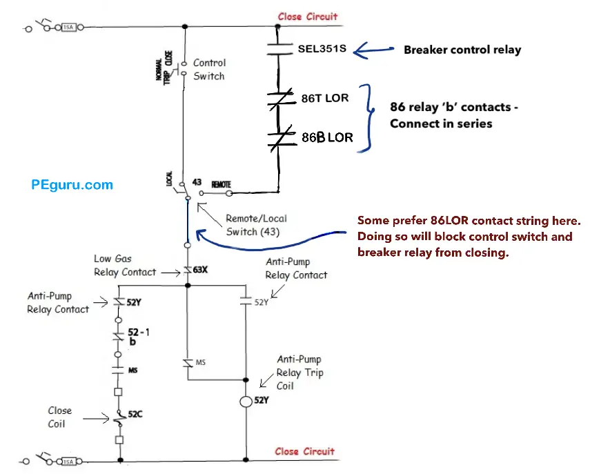
For this circuit, you must wire breaker control relay’s ‘a’ contact in series with a string of 86 lockout relay ‘b’ contacts before you hit the anti-pump relay in the close circuit. Why? Well, would you want to close a breaker into a faulted circuit? See figure 3 . In this example, you have 86T (transformer LOR) and 86B (bus LOR) ‘b’ contacts in series with ‘a’ contact of SEL351S breaker control relay. Therefore when either a transformer or a bus fault occurs, its corresponding LOR will block the SEL351S from completing the circuit.
Modern breaker control relays are programmed to check for synchronism. That is, before the breaker is closed, the relay checks the phase angle of source and load side voltage of any one phase. If the angles are out of sync, the relay logic will not allow its close control contact to operate.
The close circuit also has contacts from the Motor Switch (MS). The motor is used to charge the spring that trips-closes. The motor switch contacts don’t allow the breaker to close until it finishes its job.
Details on how to develop a protection scheme
Alright! Enough theory. Want real world design implementation? Then checkout the ebook below. Industry popular 138kV Siemens SPS2 breaker scheme used. Relaying oneline for two different substations created from scratch to explain what trips, closes, and blocks close. Thank you for supporting this blog.
Circuit Breaker Control Scheme Aleen Mohammed
- Learn how to create trip and close scheme for a high voltage circuit breaker. Not just theory but practically implemented.
Anti-Pump Relays
To prevent inadvertent multiple closing operation, breakers are fitted with anti-pump relay (52Y ANSI designation). Assume a scenario where a fault persists on a line, and a person is attempting to close a breaker on it. Although the person presses the close button for a second or two, for the breaker which operates in cycles, this duration is an eternity. With the close button pressed, the breaker attempts to open and close multiple times. Since the motor in the breaker is not rated for continuous duty, serious damage can occur.
On a final note, keep in mind that not all relays back in the control building can handle the momentary inrush current from the breaker trip coil. Case-in-point the SCADA control relays. Interposing relays like those manufactured by Potter-Brumfield are typically installed to act as the middle-man. So in our case, the SCADA relay trips an interposing relay, and this relay energizes the breaker trip coil.
Most modern microprocessor relays, especially ones made by Schweitzer, can handle inrush currents up to 30Amps and thus can be wired directly to the breaker coils.
- Breaker scheme is a web of interlocked relays and switches.
- Breaker operation is controlled by relays and switches.
- Trip contacts are wired in parallel.
- Close contacts are wired in series i.e. breaker control relay ‘a’ contact followed by a series of LOR ‘b’ contacts.
Recommended posts for you:
21 thoughts on “Power Circuit Breaker – Operation and Control Scheme”
What is the function of ms relat
MS is the motor switch. The motor in the breaker kicks in to charge the springs. You don’t want to close when the breaker springs are charging. The MS contacts inhibit breaker operation when it is charging.
Hello!!!!! I want to connect two network by using CIRCUIT BREAKER but my circuit breaker is not closing . i need some suggestions
Very good explanation illustration. I just notice that you have not mentioned the operation of MS. Kindly add to your explanation about the MS. Thanks
Could you explain MS contact in close circuit? I think ms contact connected wrong in this diagram.
ok, but 1 question. The schematic shows the circuit in a DE-ENERGIZED state. So, once the 2 switches on the positive rail and the negative rail are closed(ie power), do those 52a and 52b contacts change their states? Thanks
For Relay purposes “CLOSED” does not necesarily always mean “POWER”…. It depends on the function and how everything is connected. The 52a and b contacts, are normally open, and normally closed, which typically refers to the position during normal operations when everything is working as it should. , however if the particular function, or operation fails, or trips, then the contact would then change state from open to close, or vice versa…….. So and example is if a relay contact is open, and there is a fault somewhere, or if the transformer fails, The contact closes, and would send a signal to trip a breaker, to protect it anything else on the system from getting fried…
Very cool description. It would be nice to show say a SEL351 feeder relay in here and showing the SCADA outputs, but this is great!
What a simple and brief description of CB control circuits.Be blessed with sharing
why two anti-pump relay contacts on close circuit …??
Thanx Article is very useful to understand basics of CB circuits 🙂
good article and great explenation and will pass on to my coworkers
explain the 86 functions and were to put the relays to
Leave a Comment Cancel Reply
Your email address will not be published. Required fields are marked *
Aleen Mohammed
Connect with me
- Online Training
- Access Your Courses
- Group Registration
- The Complete Relay Testing Handbook Series
- Book Extras
- Your Digital Downloads
- Hands-On Training Class Information
- Download Our Relay Training Brochure
- TechTalk (Our Blog)
- Add Your Post to TechTalk
- We Need Your Help!
- Why Choose Valence?
- About Chris Werstiuk
- Testimonials
- Contact Valence
- Subscribe to our Mailing List
- Your Shopping Cart
- The Relay Testing Handbook
- Your Account Info
No products in the cart.
Introduction to Breaker Failure Schemes (50BF)
I presented a “ Testing Breaker Failure Schemes ” paper at the 36th annual Hands-On Relay School in 2019. Here’s the first part of the paper that will give you a basic introduction to Breaker Failure Schemes:
1. Introduction
The power system is a delicate balance between load and generation. We usually think that brownouts and blackouts are only caused by faults on the system, but they can also occur when the load is greater than the available generation; or when there is more generation available than load. Protective relays detect faults and isolate them from the rest of system before they destabilize the entire grid and cause system-wide outages. History has shown that every extra moment a fault is energized can destabilize a larger part of the power grid. All transmission system protection is designed to minimize the fault time to protect the entire grid. Every cycle counts!
Any important node on the power system will have:
- An isolating device (circuit breaker/circuit switcher) to energize and isolate a section of the power system.
- Instrument transformers (CTs/PTs) to reduce the primary voltage and/or currents to smaller, secondary values to minimize the size of protection equipment.
- A protective relay that measures the CT/PT secondaries and equipment status to detect problems on the power system that should be isolated.
- A separate power supply for the protection and isolation equipment that operates under all power system conditions.
Electrical Engineers are constantly asking themselves “What if?” questions, trying to make the power system more reliable and stable. A cost/benefit analysis is applied to each “What if?” question. More questions will be asked if the equipment is vital to power system stability, or expensive. Transmission circuit breakers have a lot of questions because they are vital to power system stability. Some of those questions and answers include:
- What if the PT fuse(s) operate? Add Loss-of-Potential logic that blocks any element that uses voltage in its calculations.
- What if the zone of protection is large enough to trip when an overload occurs? Add a Load Encroachment, or Fault Current-detector, blocking element that helps the relay tell the difference between faults and overloads.
- What if the fault is still on the circuit when you close the breaker? Add Switch-Onto-Fault logic to trip the circuit breaker immediately instead of waiting for the normal time delay.
- What if the circuit breaker trip circuit fails? Add a redundant trip circuit with a unique power supply, inputs, and trip coil.
- What if the protective relay fails? Buy a different model relay with the same functions and install it as secondary protection that detects faults and trips the circuit breaker.
- What if the trip coil circuit opens? Add Trip Coil Detection circuitry to provide an alarm if a problem with the trip coil circuit is detected.
- What if both primary and secondary protective relays fail? Add backup protection on adjacent nodes with extended time delays that gives the circuit breaker plenty of time to trip after its local relays detect a fault.
There are plenty more “What if?” questions left, but the circuit breaker is still a weak link after all the other contingencies are accounted for. Breaker fail protection answers the question: “What if the circuit breaker fails to open during a fault?”
The power system depends on transmission circuit breakers opening when the protection and control system sends an “open” command. However, any of these circuit breaker problems could prevent them from opening:
- The trip coil can’t operate when there is low, or zero, DC trip voltage at the circuit breaker.
- The trip coil(s) could be mechanically or electrically damaged and unable to operate.
- The tripping latches could be out of alignment and unable to release.
- The trip mechanism could be out-of-alignment or damaged.
- The primary dielectric might not be able to quench the arc created when the contacts open because it is contaminated, low, or missing.
- The primary contacts could be fused closed.
- The fault current could be higher than the circuit breaker’s opening ratings.
2. What Should Happen When a Fault is Detected
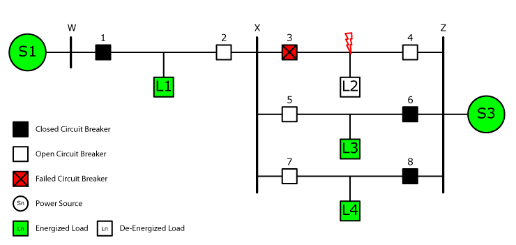
Before we dig into breaker failure schemes, let’s look at what is supposed to happen in a perfect world when a fault occurs between breakers 3 and 4, as shown in Figure 1.
Breakers 3 and 4 should both operate with no intentional time delay via their Line Distance (21), Zone 1 protection, or Line Differential (87L) protection, as shown in Figure 2. The ideal worst-case scenario happens when one relay on the line detects a Zone 1 fault and operates with no intentional time delay, then the other relay trips 15-25 cycles later after detecting a Zone 2 fault. Either way, the fault is isolated from the system with minimum disruption because L2 is the only load that is offline after the relays operate.
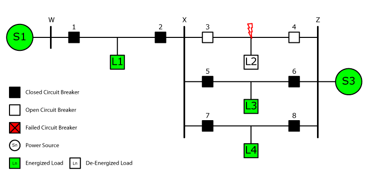
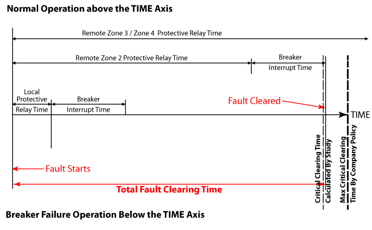
Figure 2 shows a time graph of the entire tripping process with both relays operating with no intentional time delay. The Total Fault Clearing Time in an ideal world equals the Local Protective Relay Time and the Breaker Interrupt Time. The Total Fault Clearing Time must be faster than the Critical Clearing Times, otherwise the rest of the grid may destabilize. You should notice that an element with “no intentional time delay” has a number of hidden time delays that occur in the real world. “Instantaneous” elements aren’t really instantaneous.
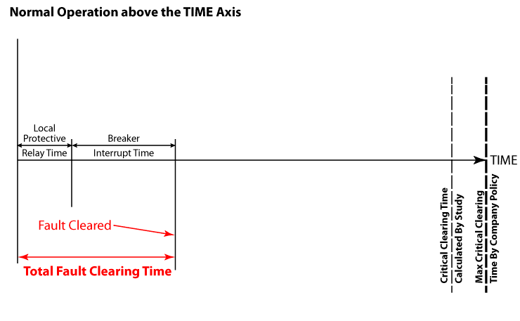
All of the information in Figure 2 can be summarized with the following descriptions:
- “TIME” is the X-axis, which organizes all time delays involved that isolate a fault from the power system.
- analyze the input waveforms,
- detect the fault with calculations or pattern recognition,
- ensure the fault is on the system longer than the expected time delay,
- send a trip signal to its internal output contacts, and
- close its internal output contacts.
- “Breaker Interrupt Time” is the amount of time that the breaker takes to open and isolate the fault when a trip signal is received under normal conditions.
- “Fault Cleared” indicates the moment that the fault has been successfully isolated from the rest of the power system.
- “Total Fault Clearing Time” is the sum total of all time delays required to isolate the fault from the rest of the power system.
- “Critical Clearing Time Calculated by Study” is the maximum amount of time that the fault can stay on the system at that specific location before the system becomes destabilized. The fault must be cleared within this time delay to prevent a cascading system-wide failure.
- “Critical Clearing Time Calculated by Company Policy” is a safety margin that the utility applies to all transmission lines to prevent system-wide cascading failures. The fault should be cleared within this time delay.
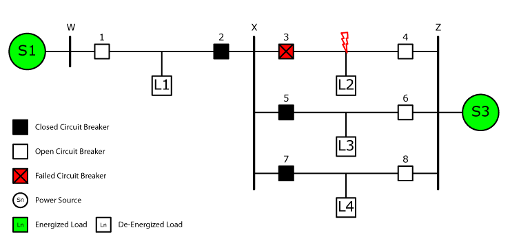
Figure 3 shows what happens when something goes wrong with the local protection and the remote Zone 2 backup protection in the relays connected to Breakers 1, 4, 6, and 8 operates instead. All four loads are now de-energized instead of just the load closest to the fault. The entire local power grid could also be in jeopardy because the delicate balance between generation and load could be tilted too far toward generation and cause problems everywhere.
The time graph in Figure 4 shows what happens when the backup protection operates. Notice that the Total Fault Clearing Time is significantly longer than it was when the local relays tripped. The time delay could be longer than the Critical Clearing Times as well, which would destabilize the entire grid.
The situation changes with a Breaker Failure scheme, as shown in Figure 5. The Breaker Failure scheme received a trip signal when the relay tripped and waited for the circuit breaker to open. The circuit breaker did not open before the Breaker Failure Timer expired, so the Breaker Failure Scheme opened all of the circuit breakers directly connected to the failed circuit breaker to isolate the fault from the system. The three non-faulted loads were still energized after the fault was cleared, as they were when the local protection operated. The Breaker Failure Scheme prevented the catastrophe that occurred when the remote backup protection operated.
The time graph in Figure 6 shows the time delays associated with a Breaker Failure scheme.
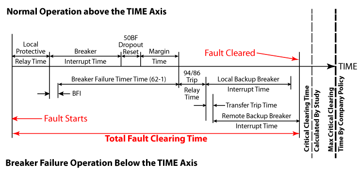
The new time delays in Figure 6 can be summarized with the following information:
- “BF Dropout Reset” allows time for the Breaker Failure element (50BF) to disarm itself after the circuit breaker opens to prevent mis-operations.
- “Margin Time” is an extra fudge factor to account for any problems that could slow the breaker opening time.
- “BFI” is the time it takes the Breaker Failure Scheme to sense the trip signal sent to the circuit breaker.
- “Breaker Failure Timer Time (62-1)” is the setting that determines how long the Breaker Failure Scheme waits before sensing that the local breaker has failed before it starts opening all of the circuit breakers required to isolate the failed circuit breaker.
- “94/86 Trip Relay Time” is the time it takes for any external relays to recognize the Breaker Failure Trip, and send a trip signal to all the associated circuit breakers that should trip to isolate the failed circuit breaker.
- “Local/Remote Breaker Interrupt Time” is the local breaker opening time to isolate the fault when a trip signal is received under normal conditions.
- “Transfer Trip Time” is the time delay that occurs when a trip signal is sent through communication equipment.
All faults should be cleared before the Critical Clearing Time. Breaker Failure Schemes allow the design engineer to ensure this happens locally without relying on backup protection.
3. Basic Breaker Failure Protection Schemes
Basic Breaker Failure Schemes are pretty straightforward, as shown in Figure 6. The Breaker Failure Timer will start if the circuit breaker is closed AND the circuit breaker receives a trip signal. If the circuit breaker opens before the Breaker Failure Timer times out, the Breaker Failure protection will disarm itself. If the Breaker Failure Timer times out, a Breaker Failure Trip command will be sent to all the other circuit breakers connected to the failed circuit breaker.

Let’s look at each of the main Breaker Failure Scheme components in detail:
A) Breaker Status (52A)
The Breaker Failure (BF) Scheme needs to know whether the circuit breaker is open or closed before it can determine if the circuit breaker has failed to open. You might think that the design engineer can simply link the 52A contact from the circuit breaker into the scheme and call it a day, but remember that the BF scheme can trip multiple breakers at once. Breaker Failure schemes are relay testers’ greatest nemesis. There are many “famous” relay testers who have unintentionally tripped a BF scheme and can regale you with the chaos created when it happens.
A good transmission engineer would never trust a small piece of plastic, like the 52A contact in a breaker, with something as important as a BF scheme. Therefore, BF schemes typically use phase and/or ground current-detectors to determine if the circuit breaker is open or closed. The breaker is considered closed if the measured current is greater than the current-detector setpoint, regardless of the 52A contact position. The circuit breaker is considered to be open if the current is less than the current-detector setpoint.
Most standards recommend setting the BF current-detectors higher than the normal load current to prevent mis-operations when a fault is not present on the system. A high current-detector setting means that the BF scheme will not open multiple breakers when an accidental Breaker Fail Initiate signal is sent under normal operating conditions, or maintenance testing. However, most current-detector settings I’ve seen in the field are set to the minimum possible settings, which means they are more sensitive, but less secure.
Most generator Breaker Fail schemes don’t use current-detectors. These schemes use the circuit breaker’s 52b status contact because a generator’s steady state contribution to a fault may be less than the recommended fault detector settings. In fact, circuit breaker (CB) contacts may be used whenever the expected current during a BF condition is less than the recommended fault detector setting. This makes the BF scheme less secure, as many people who have shut down an entire generating plant after racking out a generator breaker during maintenance testing can attest.
The generating plant shut down because the 52b contact opened when the CB was racked-out, which caused a BF Trip. From the relay’s perspective:
- The circuit breaker closed because the 52b opened.
- The undervoltage protection turned on because the circuit breaker closed.
- The undervoltage picked up because the generator voltage was lower than its setpoint. (Remember that the generator is offline and stopped for maintenance.)
- The undervoltage timer expired and sent a trip signal to the CB.
- The Breaker Fail Timer started.
- The BF protection operated the Breaker Fail Lockout Relay because the CB remained closed.
All the CBs connected to the “failed” CB opened and isolated the generating station from the rest of the system, and then heads started rolling.
This scenario is exactly why design engineers require current-detectors to determine whether the circuit breaker is open or closed, as shown in Figure 8.

B) Breaker Fail Initiate (BFI)
Any relay, or element inside a relay, that trips the circuit breaker should also send an identical Breaker Fail Initiate signal. Breaker Failure schemes with individual BF relays usually have a Breaker Failure Initiate circuit connected to the BF relay’s input(s) that are energized when a trip is sent to the circuit breaker. Manual open commands found in trip circuits are usually not included.
Relays with internal Breaker Failure elements usually have a BFI logic setting that includes every element set to trip the circuit breaker inside the relay. Other relays nearby that also trip the breaker will have a BFI output contact connected to an input in the relay. The BFI setting should also include the inputs from the other relays that trip the CB.
The BFI input should include any protection that should trip the circuit breaker.
C) Breaker Failure Timer
The Breaker Failure Scheme opens several circuit breakers and could cause havoc on the power system if it operates incorrectly. Therefore, the Breaker Failure Timer (62BFTD) delay should be longer than:
- the normal circuit breaker opening time, and
- the time necessary for any arcs to be quenched after the circuit breaker opens, and
- the BF element to detect that the CB is open and disarm itself, and
- a margin of time to account for unexpected circumstances to give the CB plenty of time to operate before all the other circuit breakers are tripped by the BF Scheme.
A typical BFT delay is between 15 and 25 cycles.
Did you like this post?
You can share it with these links:
About the Author
Chris Werstiuk
Chris is an Electrical Engineering Technologist, a Journeyman Power System Electrician, and a Professional Engineer. He is also the Author of The Relay Testing Handbook series and founder of Valence Electrical Training Services. You can find out more about Chris here .
Read More Articles:
The Over-Excitation Testing (24) Chapter is Complete. What Should be in the Synchronizing Chapter (25)?
How to Test Breaker Failure Schemes
Leave a Reply
Your email address will not be published. Required fields are marked *
I am very much happy and satisfied by these complete explanations on the topics of Relay functioning. Thank You very much
Thanks Chris, it is a neat and clear explanation on 50BF.. found it useful!
Circuit Breaker Schematic Diagram
A schematic diagram is a drawing that shows electrical system circuitry with symbols that depict electrical devices and lines representing conductors.
Only qualified persons should review schematic diagrams and perform work on circuit breakers. A qualified person is a person who has special knowledge, training, and experience in the installation, programming, maintenance, and troubleshooting of electrical circuit breaker equipment and also has the safety skills and knowledge that allow him/her to perform the task safely.
Schematic diagrams are required for the setup and operation of common circuit breakers from OEMs such as ABB/ITE, General Electric, and Westinghouse/Cutler- Hammer.
Many Low-Voltage Circuit Breakers (LVCBs) and virtually all medium-voltage metal-clad circuit breakers use electrically operated mechanisms. Electrically operated circuit breakers have trip and close circuits, a spring-charging motor, and indicator lights. Understanding how these control circuits function is important when troubleshooting circuit breakers. It is standard protocol to show the control circuits for a circuit breaker in a schematic diagram in a de-energized condition just as it would be sitting in a cubicle with no control power applied.
Interpreting Common Circuit Breaker Schematic Diagrams
Abb circuit breaker schematic diagram.
With an ABB/ITE K-Line circuit breaker, the contact marked “CPS” (control power switch) on the schematic is used to disable the motor charging circuit and would normally be closed.

SCHEMATIC DIAGRAMS —ABB
When the circuit breaker is racked into a cubicle and is connected to control power, the following occurs:
- The spring charging motor immediately runs.
- The closing springs charge.
- Contact limit switches 1 and 3 (LS1 and LS3) open and shut off the motor.
- Contact LS2 closes and enables 52X (closing control coil).
- Contact 52b is closed because the circuit breaker is open.
The circuit breaker is now enabled to close and will remain in this condition until the CLOSE button is pressed. It is typical for the remote operating switch, identified as “Remote Close” on this drawing, to have a contact that stays closed when operated, as opposed to a momentary close contact. This means that control power is available to the circuit at all times that the control switch is in the closed position. When the remote close switch is operated, the following occurs:
- The circuit breaker main contacts close and discharge the closing springs.
- LS1 and LS3 close, but the motor circuit is disabled by 52b, which is now open.
- LS2 opens and disables the closed circuit.
- LS3 closing energizes 52Y (anti-pump coil), which in turn closes 52Y/1 and opens 52Y/2.
- Contact 52Y/1 forms a parallel path, known as a seal-in circuit, around LS3. This keeps 52Y coil energized until control power is removed.
- Contact 52Y/2 remains open as long as the anti-pump (lockout) coil is energized. The circuit breaker remains in this condition until it trips. When it does the trip, the following occurs:
- Contact 52b recloses.
- LS1 and LS3 close and LS2 open.
- LS1 allows the spring-charging motor to charge the springs, causing LS1 and LS3 to open and LS2 to close.
During this sequence, 52Y remains energized due to the seal-in contact (52Y/1). Ordinarily, the circuit breaker would now be enabled to close, but 52Y prevents this by keeping the 52Y/2 contact open. To close the circuit breaker, control power would have to be removed by resetting the remote close switch to the open position. As a result, 52Y would be de-energized, which would close 52Y/2 and open 52Y/1.
General Electric Circuit Breaker Schematic Diagram
In a General Electric Power/Vac medium-voltage circuit breaker schematic diagram, the circuit breaker is shown de-energized with the circuit breaker open and no control power applied.

SCHEMATIC DIAGRAMS —GENERAL ELECTRIC
When control power is applied, the following occurs:
- The spring charging motor (M) energizes.
- Coil 52Y energizes (prevents a closing operation until the springs are charged).
- When the springs are charged, 52/SM/LS locations open.
- Since the control switch (CS) is open, 52Y de-energizes.
The circuit breaker is now in a position to close. To close the circuit breaker, the remote CS is turned to the closed position. In the closed position, the following occurs:
- Closing coil 52X becomes energized and releases the closing springs.
- 52 SM/LS locations close because the springs are discharged.
- Auxiliary contact 52b in the closing control circuit changes position as well as the 52a contacts in the trip circuit
- Coil 52Y is energized. Three contacts change position, which opens the circuit to 52X and close the 52Y seal-in contact.
When the breaker is fully set in the closed position, 52/ CL/MS closes, allowing the spring-charging motor to operate. When the springs are charged, 52/ SM/LS opens, stopping the spring-charging motor. As long as the remote control switch contacts remain closed, 52Y is energized, preventing repeated automatic reclosing (anti-pump). To trip or open the circuit breaker once the circuit breaker is closed, the following must occur:
- Both 52a contacts are closed because the circuit breaker is closed.
- Terminals 9 (+) and 10 (–) are connected to the DC voltage source.
- Closing CS/T energizes 52/TC (trip coil), opening the circuit breaker.
Westinghouse/Cutler-Hammer Circuit Breaker Schematic Diagram
In a Westinghouse/Cutler-Hammer schematic diagram, the circuit breaker is shown open, and the closing springs are shown discharged. As soon as power is applied to the control circuit (terminals 7 and 4), the spring charging motor is energized, and the closing springs charge. Once the springs are charged, the limit switch (LS) changes from the closed position to the open position on wire 67, and the LS contact in wire 65/66 closes. This disables the spring charging motor and enables the closing circuit.

SCHEMATIC DIAGRAMS —WESTINGHOUSE
At this point, the anti-pump coil is short-circuited because the normally open LS contact closes. The “b” contacts are closed when the circuit breaker main contacts are open. When the CS is closed, the following occurs:
- The spring release (SR) coil is energized and allows the circuit breaker main contacts to close.
- Both limit switches change position. The spring charging circuit is enabled, and the spring release coil is disabled.
- Both “b” contacts open. One contact de-energizes the green light, while the other contact disables the spring charging motor, anti-pump coil, and spring release coil.
- The close contact in the CS remains closed, even when the handle is released, as it is a maintain contact.
- The “a” contact on wire 68 closes, which enables the shunt trip (ST) coil.
- The red indicator light illuminates.
The circuit breaker remains in this state until the trip coil is energized by a relay operation. When the trip coil is energized, the circuit breaker main contacts open, which closes both b contacts. The green light illuminates, and the spring charging motor is energized, which charges the closing springs.
When the springs are charged, both LSs change position. One LS de-energizes the motor, and the other energizes the anti-pump coil (Y). The spring release is not energized at this time because the Y contact opens and disables the spring release coil. The Y coil is energized because the CS closed contact is a maintain contact. A maintain contact stays closed even though the CS handle is released. If the CS is turned to the trip position, it will open the close/maintain contact in the CS, and the circuit breaker cannot close automatically.
The CS must be reset to the trip position at this time to reclose the circuit breaker. To trip the circuit breaker open, the trip coil (ST) is connected directly between the positive and negative power terminals. Once 52a contact closes (when the circuit breaker closes), the CS can be operated to the trip position. This will trip the circuit breaker and open the close/maintain contact with the CS.

Recent Orders
Your account.
Checkout $0.00
- Product Returns (RMAs)
- Pay Proforma Invoices
- Pay Freights
- Invoices / Invoice Reprint
- Quotes / Favs / BOMs
- Packing List Reprint
- My Product Docs
- Credit Application
- Barcode / RFID / Vision
- Bulk Wire & Cable
- Cables (Terminated)
- Circuit Protection / Fuses / Disconnects
- Communications
- Drives & Soft Starters
- Enclosure Thermal Management & Lights
- Enclosures & Racks
- HMI (Human Machine Interface)
- Hydraulic Components
- Motion Control
- Motor Controls
- Pneumatic Components
- Power Products (Electrical)
- Power Transmission (Mechanical)
- Process Control & Measurement
- Programmable Controllers
- Pushbuttons / Switches / Indicators
- Relays / Timers
- Sensors / Encoders
- Stacklights
- Structural Frames / Rails
- Tools & Test Equipment
- Water (Potable) Components
- Wiring Solutions
- Retired Products
- E-newsletter
- Online PDF Catalog
- Order Catalog On USB
- Download Price List
- Video Tutorials
- Company Reviews
- Job Opportunities
- Product Application Stories
- Learning Library
- Affordable Training
- Free Online PLC training
- Find an authorized integrator
- Track Your Order
- Pay Open Invoices
- Product Comparison Feature - How To Video
- Cybersecurity
- Programmable Logic Controllers
- Productivity1000 PLCs
- Productivity2000 PLCs
- Productivity3000 PLCs
- ProductivityCODESYS
- LS Electric XGB Series PLCs
- ProductivityOpen
- Do-more H2 PLCs or Do-more T1H Series
- Do-more BRX PLCs
- C-more Touch Panels
- AC & DC Drives
- PLC Family Selector
- P1000 PLC Systems
- P2000 PLC Systems
- P3000 PLC Systems
- CLICK PLC Systems
- Do-more ® BRX PLC Systems
- LS-Electric ® XGB PLC Systems
- Productivity ® Open Systems
- Datalogic ® Safety Light Curtains
- LS-Electric ® Servo Systems
- Nitra ® Pneumatic Grippers
- Object Detection (Sensors)
- PAL Controller Configurator
- Precision Gearbox Selector
- Protos X ® Field I/O
- Quadritalia ® Modular Enclosures
- Stellar ® Soft Starters
- Stepper System Selector
- SureFrame T-slot Extrusion
- SureMotion ® XYZ Gantry
- SureServo2 ® System Selector
- SureStep ® Linear Actuators
- Timing Belts & Pulleys
- Werma ® Stacklights
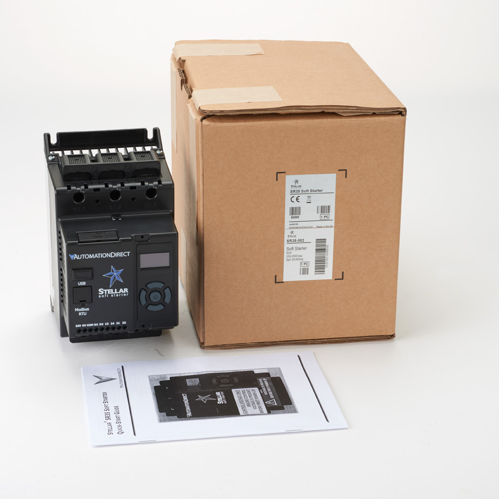
Stellar SR35 series basic soft starter, 52A, 110-240 VAC at 1-phase/208-460 VAC at 3-phase, Trip Class 10/20/30, rated for 5 start/hour, internally bypassed.
Stride Interactive Product Tour Request

Report An Issue
Delivery Calculation
SR35-052 Specifications
Technical Specifications
SR35-052 Product Notes
SR35-052 Technical Questions
Sr35-052 downloads.
Support Resources
SR35-052 Compliance Information
Agency compliance & certifications.
Conflict Minerals Information
SR35-052 Related Videos

Application Stories
{{appStory.pagetextAsHTML.raw}}
SR35-052 What's in the Box
What's in the box.
Withdraw product rating confirmation
Item ' product ', company information.

Voted #1 mid-sized employer in Atlanta Check out our job openings
Check Inventory Levels

The following navigation utilizes arrow, enter, escape, and space bar key commands. Left and right arrows move through main tier links and expand / close menus in sub tiers. Up and Down arrows will open main tier menus and toggle through sub tier links. Enter and space open menus and escape closes them as well. Tab will move on to the next part of the site rather than go through menu items.
- 52A South Kedzie

52A South Kedzie
Bus route information.
Service description: See schedule for full details.
First bus/last bus
Spans of service below show when first bus departs terminal of origin through last bus departs terminal of origin. First and last buses reach mid-route stops later than these times-see schedule or use trip planner for specific times when service works for you.
(Precise hours of service may vary depending on where along the route you are.)
Service alerts
There are no active or scheduled alerts at this time.
RSS Feed: #52A South Kedzie Alerts

Note that Sunday schedules apply on the following holidays: New Year’s Day, Memorial Day, Independence Day, Labor Day, Thanksgiving and Christmas (and/or on their dates of observance).
Timetable update
We routinely adjust schedules to help make service operate more efficiently and to account for seasonal ridership patterns.
Several train routes will have their schedules updated effective April 7.
View the updated route timetables
CTA bus 52A
South kedzie, cta bus 52a stop list and cta bus tracker 52a.
The CTA bus 52A - South Kedzie serves {count_of_stops} bus stops in Chicago departing from {first_stop} and ending at {last_stop}. Scroll down to see upcoming bus 52A times at each stop. You can also see connecting lines for the bus 52A route at each stop, including connections to the 'L' or other transit options, so you can understand where and when to transfer. The CTA bus tracker 52A shows the next scheduled departure from the CTA. The full CTA 52A schedule with real-time tracker data is available in the app .
The CTA bus 52A - South Kedzie route map is shown above. The route map shows you an overview of all the stops served by the CTA bus 52A to help you plan your trip on CTA. Opening the app will allow you to see more detailed information about the route on a map including stop specific alerts, such as stops that have been closed or moved. You can also use the included CTA tracker in the app to see the location of vehicles in real-time on the route map so you know when the 52A bus is approaching your stop.
CTA bus 52A Service Alerts
Open the app to see more information about any active disruptions that may impact the bus 52A schedule, such as detours, moved stops, trip cancellations, major delays, or other service changes to the bus route. The app also allows you to subscribe to receive notifications for any service alert issued by CTA so that you can plan your trip around any active or future disruptions.
CTA bus 52A FAQ
What time does the next cta bus 52a depart from {first_stop}.
The next bus 52A leaves {first_stop} at {first_stop_first_time}, and arrives at {last_stop} at {last_stop_first_time}. The total trip time for the next CTA bus 52A is {number_of_minutes} minutes.
Is the CTA bus 52A running on time, early or late?
You can track your bus on a map, monitor real-time updates, and see adjustments to the CTA 52A schedule by downloading the app .
When does the next CTA bus 52A arrive?
You can see the next CTA bus 52A times in the app as well as future departure times for the bus 52A.
How many bus stops are there for the CTA bus 52A?
There are {count_of_stops} stops on the CTA bus 52A.
Is the CTA bus 52A usually crowded?
You can find real-time information on CTA bus 52A crowding levels in the app (available in select cities or on select trips). You can also see predictions on how crowded the bus will be when it gets to your bus stop.
Is the CTA bus 52A currently running?
Find out the current status for the CTA bus 52A in the app
What is the closest CTA bus 52A stop to me?
Open the app to see your location on a map and find the closest bus 52A stop to where you are.
Other CTA bus schedules, routes and maps
- 53A South Pulaski
- 54A North Cicero / Skokie Blvd.
- 54B South Cicero
- 55 Garfield
- 55A 55th / Austin
- 55N 55th / Narragansett
- 56 Milwaukee
- 59 59th / 61st
- 60 Blue Island / 26th
- 62H Archer / Harlem
Other transit modes in Chicago
- 'L'
Never miss your bus again. Download Transit.

IMAGES
VIDEO
COMMENTS
A form 'b' contact represents a Normally Closed (N.C.) contact.It operates exactly opposite of what an 'a' does.When the breaker is open, the 52b contacts are closed. When the breaker is closed, the 52b contacts are open. With the 52a contact in the trip circuit (as shown in the scheme above), once the breaker opens, this contact opens too.
52a I Circuit Breaker Trip Coil and Auxiliary Contact. Evolving Protective Relay Designs • Electromechanical relays • Electronic analog relays - solid state (transistors, integrated circuits) Microprocessor = = = = = = = = = = = = Tripping }
In Electrical Power Systems and Industrial Automation, ANSI Device Numbers can be used to identify equipment and devices in a system such as relays, circuit breakers, or instruments.The device numbers are enumerated in ANSI/IEEE Standard C37.2 "Standard for Electrical Power System Device Function Numbers, Acronyms, and Contact Designations". Many of these devices protect electrical systems and ...
Add Trip Coil Detection circuitry to provide an alarm if a problem with the trip coil circuit is detected. ... (52A) The Breaker Failure (BF) Scheme needs to know whether the circuit breaker is open or closed before it can determine if the circuit breaker has failed to open. You might think that the design engineer can simply link the 52A ...
Conversely, if the 52a contact fails to open correctly, a false failure can be indicated, resulting in an unnecessary backup trip, even though the main contacts have successfully interrupted the current. In most instances, a significant run of cabling is required to send the 52a indication to the breaker failure scheme. This
the 50BFP threshold, the CB 52a contact does not deassert, and the logic issues a breaker failure trip (BFT). The BFT signal is typically sent to the bus protective relay, which then issues a trip si gnal to all associated CBs that are preconfigured to isolate the fault in the event of the CB failing. The trip signal can also
To trip or open the circuit breaker once the circuit breaker is closed, the following must occur: Both 52a contacts are closed because the circuit breaker is closed. Terminals 9 (+) and 10 (-) are connected to the DC voltage source. Closing CS/T energizes 52/TC (trip coil), opening the circuit breaker.
that could be used and configured to energize two trip coils from their separate DC circuits. Engineering should be consulted for test set-up options, and company safety procedures should be followed. If the trip coils are installed properly the series 52a contacts should interrupt the trip coil currents.
52A TRIP (OUT1) CLOSE (OUT2) Schweitzer Engineering Laboratories, Inc. SEL-501 Data Sheet 5 Breaker Failure Protection Figure 3 SEL-501 Relay Breaker Failure Logic General-Purpose Timer Timer Ranges (62 Device) Pickup: 0-16,000 cycles Dropout: 0-16,000 cycles The timers are completely independent of the relay
Interchange 52A Additional Information. Calculate Your Tolls and Trip Distances | Find Interchange 52A on the Thruway Map. Interchange 52A - (I-90) - Buffalo - William Street Connecting Routes. William Street
is connected in parallel to the trip contact(s) of the protection relay(s), as shown in the figure below. The drop-out time delay is 0,8 s or more, in order to not give a signal during normal fault clearance, when the trip contact is closed. Trip Circuit open alarm 52a is a closing auxiliary contact in the circuit breaker that is closed when the
TC 1 Trip Coil 1 52a Breaker Auxiliary For example, consider an inadvertent short-circuit from the +DC bus to ground. Before the inadvertent ground occurs, the current flowing through R1 and R2 is equal. Thus, under normal operation, R1 and R2 each support a voltage equal to half the total battery voltage. The
52A Trip Coil + _ Trip Output 52A Trip Coil + _ Figure 2a: Trip Circuit Using Conventional Relaying Figure 2b: Using Microprocessor-Based Relay By using programmable logic, we require only one output contact, significantly reducing wiring and simplifying the control circuit. Using Programmable Logic and Control Inputs to Provide Fast Bus Protection
These schemes are the frequently used and are provided in most medium voltage switchgear applications. 1. General - Functional Requirements. A protection relay is usually required to trip a circuit breaker (CB). The power required by the trip coil of the CB may range from 50 W for a small distribution CB to 3000 W for a large EHV CB.
Stellar SR35 series basic soft starter, 52A, 110-240 VAC at 1-phase/208-460 VAC at 3-phase, Trip Class 10/20/30, rated for 5 start/hour, internally bypassed. Software, Firmware, Configuration files and other resources.
Suffolk County Transit bus Time 52A Service Alerts. Open the app to see more information about any active disruptions that may impact the 52A bus schedule, such as detours, moved stops, trip cancellations, major delays, or other service changes to the bus route. The app also allows you to subscribe to receive notifications for any service alert issued by Suffolk County Transit so that you can ...
52a 52a trip coil phase 1 ct phase 2 ct phase 3 ct zero sequence ground ct load input input b a ground programmabl e controller shielded twisted pair * * * termination 120 ohm resistor 1nf/50v bi-directional capacitor. heavy copper conductor or braided wire 4000 feet max./ max. of 32 relays switchgear
Allen-Bradley® Motor Circuit Breaker, 4A, 600VAC, 3P, 52A Trip SKU # 66207426033 Manufacturer Series: 140M Set Required Date Required by: (edit) Qty. Please enter a valid quantity Unit of Sale: Each Order in multiples of: 1. Add to Cart Adding to Cart... Unable to add item(s) to cart. Please try again. ...
The 52a contact is used as another optional input to the reclosing function to indicate there was a change in both the 52b and 52a contacts in the breaker. If there wasn't a change in both, then the reclosing relay locks out the breaker. Wire the 52a status contact of the breaker being controlled to the existing 52a input of the relay.
service aux. trip trip phase 1 phase 2 phase 3 groundcurre nt inpu t. g1 h1 g2 h2 g3 h3 g4 h4. shiel d fgnd sgnd contro l power filter ground safety ground chassis ground scre w. rs422tx option rs485 (rs422 rx) 804600d9.dwg. line. b c trip coil control power a circuit breaker 52a. trip coil phase 1 ct phase 2 ct phase 3 ct zero sequence ground ...
Spans of service below show when first bus departs terminal of origin through last bus departs terminal of origin. First and last buses reach mid-route stops later than these times-see schedule or use trip planner for specific times when service works for you. 115th/Springfield north to Kedzie/49th (accessible) (Orange) 4:15a-10:10p weekdays, 4 ...
CTA bus 52A Service Alerts. Open the app to see more information about any active disruptions that may impact the bus 52A schedule, such as detours, moved stops, trip cancellations, major delays, or other service changes to the bus route. The app also allows you to subscribe to receive notifications for any service alert issued by CTA so that you can plan your trip around any active or future ...
Trip Coil 52A (—) (+) Trip Circuit Direct or Multiplexed Fiber-Optic Connection TC 52B (—) (+) Close Circuit CC 52A A B C (—) (+) Transfer contacts provide flexible remote control capabilities. The R1 and R2 contacts in one SEL-387L Relay mirror the T1 and T2 inputs from the remote end relay. Use them for remote signaling or control.