- Activity Diagram (UML)
- Amazon Web Services
- Android Mockups
- Block Diagram
- Business Process Management
- Chemical Chart
- Cisco Network Diagram
- Class Diagram (UML)
- Collaboration Diagram (UML)
- Compare & Contrast Diagram
- Component Diagram (UML)
- Concept Diagram
- Cycle Diagram
- Data Flow Diagram
- Data Flow Diagrams (YC)
- Database Diagram
- Deployment Diagram (UML)
- Entity Relationship Diagram
- Family Tree
- Fishbone / Ishikawa Diagram
- Gantt Chart
- Infographics
- iOS Mockups
- Network Diagram
- Object Diagram (UML)
- Object Process Model
- Organizational Chart
- Sequence Diagram (UML)
- Spider Diagram
- State Chart Diagram (UML)
- Story Board
- SWOT Diagram
- TQM - Total Quality Management
- Use Case Diagram (UML)
- Value Stream Mapping
- Venn Diagram
- Web Mockups
- Work Breakdown Structure

New Mobile Tourist Guide Use Case [classic]
You can easily edit this template using Creately. You can export it in multiple formats like JPEG, PNG and SVG and easily add it to Word documents, Powerpoint (PPT) presentations, Excel or any other documents. You can export it as a PDF for high-quality printouts.
- Flowchart Templates
- Org Chart Templates
- Concept Map Templates
- Mind Mapping Templates
- WBS Templates
- Family Tree Templates
- Network Diagram Templates
- SWOT Analysis Templates
- Genogram Templates
- Activity Diagram
- Class Diagram
- Collaboration Diagram
- Component Diagram
- Data Flow Diagrams(YC)
- Deployment Diagram
- Object Diagram
- Sequence Diagram
- State Chart Diagram
- Use Case Diagram
Related Templates
Academia.edu no longer supports Internet Explorer.
To browse Academia.edu and the wider internet faster and more securely, please take a few seconds to upgrade your browser .
Enter the email address you signed up with and we'll email you a reset link.
- We're Hiring!
- Help Center

Tourism Guide System Project Documentation

2018, Borhan Alobaidy
Related Papers
Charles Heric
Qinghe XIAO
Jessys Melgar
Tuncay ALTUN
idil ece şener
Usman Alhaji Buba
Randan S A D I Q Halfan
International Journal of Sino-Western Studies, No. 17
Paulos Huang , Tao YU
S o c i a l C a r e i n P r o t e s t a n t S p i r i t O n t h e R o l e a n d S i g n i f i c a n c e o f t h e R e f o r m a t i o n i n t h e F o r m a t i o n o f N o r d i c We l f a r e S t a t e S y s t e m A b s t r a c t : T h i sp a p e ri st oe x a m i n et h ec h a n g e so fN o r d i cw e l f a r es t a t e ss y s t e ma n dt os t u d yt h er o l ea n ds i g n i f i c a n c eo f b a s i cd o c t r i n e s , e t h i c sa n dc o n c e p t si nt h e R e f o r m a t i o ni nt h ef o r m a t i o no fN o r d i c w e l f a r es t a t es y s t e m , b a s e do nt h e P r o t e s t a n t i s m a f t e r t h e R e f o r m a t i o n.Mo r e o v e r , t h e P r o t e s t a n t s o c i a lc o n c e r n t h e o r y a n d p r a c t i c e f o r m e d i n t h e R e f o r m a t i o nh a v ep l a y e da ni mp o r t a n tr o l e i np r o m o t i n gt h ed e v e l o pm e n to f t h eN o r d i cw e l f a r es t a t es y s t e m , w h i c hi sa l s o t h ef o c u so ft h i ss t u d y. T h r o u g ha n a l y z i n g , t h i sp a p e ra i m st om a k et h er e a l i s t i cd e v e l o pm e n to fP r o t e s t a n ts p i r i th a v ea n e wp e r s p e c t i v e , a n dt oh a v ead e e p e ru n d e r s t a n d i n go fs i g n i f i c a n c eo ft h es o c i o G p o l i t i c a lp h i l o s o p h yo ft h eR e f o r m a t i o n. K e y Wo r d s : R e f o r m a t i o n ; P r o t e s t a n tS p i r i t ; S o c i a lC a r e ; N o r d i cWe l f a r eS t a t eS y s t e m A u t h o r : YU T a o , A s s o c i a t eP r o f e s s o r , C o l l e g eo fP h i l o s o p h y , N a n k a iUn i v e r s i t y , T i a n j i n , 3 0 0 3 5 0 , C h i n a , T e l : 8 6 G 1 3 7 G 5 2 3 4 G 8 3 6 2 ; Em a i l : t o w a v e@1 2 6. c o m 1 I n t r o d u c t i o n T h eP r o t e s t a n ts p i r i t , a sad i r e c tp r o d u c to ft h eR e f o r m a t i o n , r e l i e so nar e l i g i o u sb e l i e fw i t ht h e p o w e ro ft r a n s c e n d e n t a lG o dt or a t i o n a l i z et h ew e a l t ha c c umu l a t i o ni nt h em o r t a l l i f e , wh i c hp r o v i d e s t h ep r o o fo f " c a l l i n g " o fr e l i g i o u st h e o l o g yf o rp e o p l es m o t i v e sa n di n t e n t i o n st o m a k ep r o f i t si n s e c u l a rs o c i e t y. F r o mt h i sp o i n to fv i e w , P r o t e s t a n ts p i r i tc a nb ed e f i n e da st h es um o fas e r i e so f e t h i c s , i d e o l o g ya n dv a l u es t a n d a r d s , w h i c ha r ed e r i v e df r o mP r o t e s t a n td o c t r i n e sa n da r er e c o g n i z e d , T h ew e l f a r es t a t es y s t e mi sn o tas i mp l ec omb i n a t i o no ft h ee t ym o l o g y " w e l f a r es t a t e " a n d " s y s t e m " . F r om t h ed i m e n s i o no fs o c i o G p o l i t i c a lp h i l o s o p h y , " s y s t e m " i ss u c hh i s t o r i c a le x i s t e n c e w i t hn o r m a t i v e m e a n i n g , i n c l u d i n ge n t i t ya n dn o n G e n t i t y. A sa ni n t e r m e d i a r yb e t
RELATED PAPERS
O8I7 I77O I57I MAXINDO JASA SEWA TRUK JAWA TIMUR
Journal of Thoracic Oncology
Jeremy Squire
Remote Sensing of Environment
George Nagy
Yıldırım Beyazıt Hukuk Dergisi
Melikşah ÇIRAKOĞLU
David Fernandes
Prof. Ranjan Chaudhuri
LUIS ENRIQUE CALLE RETO
South African Journal of Agricultural Extension (SAJAE)
Hlekani Kabiti
ACS Applied Materials & Interfaces
Kazuhiro MARUMOTO
International Journal of Linguistics
STEPHEN ODUOR
Adi Gunawan
Eva Göransson
Open-File Report
Darrell Herd
Sandra Parra
Journal of Tikrit University for Humanities
Suhaib Alghadhanfary
IIUM Engineering Journal
rafael ferreira dos santos
Molecular Pharmacology
Marcia Hiriart
Journal of Cystic Fibrosis
Iranian journal of medical sciences
Rogelio Coronado
Applied and Environmental Microbiology
Miia Pitkaranta
British Polymer Journal
Karel Petrak
Revista Brasileira de Educação Médica
João Campos
Jacek Pasternak
Journal of Lumbini Medical College
Indrajit Banerjee
DergiPark (Istanbul University)
Nalan Kangal
RELATED TOPICS
- We're Hiring!
- Help Center
- Find new research papers in:
- Health Sciences
- Earth Sciences
- Cognitive Science
- Mathematics
- Computer Science
- Academia ©2024
Home » UML » A Comprehensive Guide to Use Case Modeling
A Comprehensive Guide to Use Case Modeling
- Posted on September 12, 2023
- / Under UML , Use Case Analysis
What is Use Case Modeling?
This is a technique used in software development and systems engineering to describe the functional requirements of a system. It focuses on understanding and documenting how a system is supposed to work from the perspective of the end users. In essence, it helps answer the question: “What should the system do to meet the needs and goals of its users?”

Key Concepts of Use Case Modeling
Functional Requirements : Functional requirements are the features, actions, and behaviors a system must have to fulfill its intended purpose. Use case modeling is primarily concerned with defining and capturing these requirements in a structured manner.
End User’s Perspective : Use case modeling starts by looking at the system from the viewpoint of the people or entities (referred to as “actors”) who will interact with the system. It’s essential to understand how these actors will use the system to achieve their objectives or perform their tasks.
Interactions : Use case modeling emphasizes capturing the interactions between these end users (actors) and the system. It’s not just about what the system does in isolation; it’s about how it responds to user actions or requests.
The Basics of Use Cases:
- A use case is a description of how a system interacts with one or more external entities, called actors, to achieve a specific goal.
- A use case can be written in textual or diagrammatic form, depending on the level of detail and complexity required.
- A use case should capture the essential and relevant aspects of the interaction, such as the preconditions, postconditions, main flow, alternative flows, and exceptions.
What is a Use Case Diagram?
A use case diagram is a graphical representation used in use case modeling to visualize and communicate these interactions and relationships. In a use case diagram, you’ll typically see actors represented as stick figures, and the use cases (specific functionalities or features) as ovals or rectangles. Lines and arrows connect the actors to the use cases, showing how they interact.
- Actors : These are the entities or users outside the system who interact with it. They can be people, other systems, or even external hardware devices. Each actor has specific roles or responsibilities within the system.
- Use Cases : Use cases represent specific functionalities or processes that the system can perform to meet the needs of the actors. Each use case typically has a name and a description, which helps in understanding what it accomplishes.
- Relationships : The lines and arrows connecting actors and use cases in the diagram depict how the actors interact with the system through these use cases. Different types of relationships, such as associations, extend relationships, and include relationships, can be used to specify the nature of these interactions.
How to Perform Use Case Modeling?
- To understand a use case, you need to identify the actors and the use cases involved in the system. An actor is an external entity that has a role in the interaction with the system. An actor can be a person, another system, or a time event.
- A use case is a set of scenarios that describe how the system and the actor collaborate to achieve a common goal1. A scenario is a sequence of steps that describe what happens in a specific situation1. Actors in Use Case Modeling:
- Actors are represented by stick figures in a Use Case diagram. Actors can have generalization relationships, which indicate that one actor inherits the characteristics and behaviors of another actor. For example, a Student actor can be a generalization of an Undergraduate Student actor and a Graduate Student actor.
- Actors can also have association relationships, which indicate that an actor is involved in a use case. For example, an Instructor actor can be associated with a Grade Assignment use case.
Relationships Between Actors and Use Cases:

- An include relationship is a dependency between two use cases, where one use case (the base) incorporates the behavior of another use case (the inclusion) as part of its normal execution.
- An include relationship is represented by a dashed arrow with the stereotype «include» from the base to the inclusion.
- An include relationship can be used to reuse common functionality, simplify complex use cases, or abstract low-level details
- An extend relationship is a dependency between two use cases, where one use case (the extension) adds some optional or exceptional behavior to another use case (the base) under certain conditions.
- An extend relationship is represented by a dashed arrow with the stereotype «extend» from the extension to the base.
- An extend relationship can have an extension point, which is a location in the base use case where the extension can be inserted.
- An extension point can be labeled with a name and a condition
Creating Effective Use Cases:
- A system boundary is a box that encloses the use cases and shows the scope of the system.
- A system boundary helps to distinguish what is inside the system (the use cases) and what is outside the system (the actors).
- A system boundary should be clearly labeled with the name of the system and its version1.
- A use case goal is a statement that summarizes what the use case accomplishes for the actor.
- A use case goal should be specific, measurable, achievable, relevant, and testable.
- A use case scenario is a sequence of steps that describes how the actor and the system interact to achieve the goal.
- A use case scenario should be complete, consistent, realistic, and traceable.
- A use case description is a textual document that provides more details about the use case, such as the preconditions, postconditions, main flow, alternative flows, and exceptions.
- A use case description should be clear and concise, using simple and precise language, avoiding jargon and ambiguity, and following a consistent format.
- A use case description should also be coherent and comprehensive, covering all possible scenarios, outcomes, and variations, and addressing all relevant requirements.
- A use case template is a standardized format that helps to organize and present the use case information in a consistent and structured way.
- A use case template can include various sections, such as the use case name, ID, goal, actors, priority, assumptions, preconditions, postconditions, main flow, alternative flows, exceptions, etc.
- A use case documentation is a collection of use cases that describes the functionality of the system from different perspectives.
- A use case documentation can be used for various purposes, such as communication, validation, verification, testing, maintenance, etc.
Use Case Modeling Best Practices:
- Identify the key stakeholders and their goals, and involve them in the use case development process
- Use a top-down approach to identify and prioritize the most important use cases
- Use a naming convention that is consistent, meaningful, and descriptive for the use cases and actors
- Use diagrams and textual descriptions to complement each other and provide different levels of detail
- Use relationships such as extend, include, and generalization to show dependencies and commonalities among use cases
- Review and validate the use cases with the stakeholders and ensure that they are aligned with the system requirements
Use Case Modeling using Use Case Template
Problem description: university library system.
The University Library System is facing a range of operational challenges that impact its efficiency and the quality of service it provides to students, faculty, and staff. These challenges include:
- Manual Borrowing and Return Processes : The library relies on paper-based processes for book borrowing, return, and tracking of due dates. This manual approach is prone to errors, leading to discrepancies in record-keeping and occasional disputes between library staff and users.
- Inventory Management : The current system for managing the library’s extensive collection of books and materials is outdated. The lack of an efficient inventory management system makes it difficult to locate specific items, leading to frustration among library patrons and unnecessary delays.
- Late Fee Tracking : Tracking and collecting late fees for overdue books are challenging tasks. The library staff lacks an automated system to monitor due dates and assess fines accurately. This results in a loss of revenue and inconvenience for users.
- User Account Management : User accounts, including library card issuance and management, rely on manual processes. This leads to delays in providing access to library resources for new students and difficulties in updating user information for existing members.
- Limited Accessibility : The current library system lacks online access for users to search for books, place holds, or renew checked-out items remotely. This limitation hinders the convenience and accessibility that modern students and faculty expect.
- Inefficient Resource Allocation : The library staff often face challenges in optimizing the allocation of resources, such as books, journals, and study spaces. The lack of real-time data and analytics makes it difficult to make informed decisions about resource distribution.
- Communication Gaps : There is a communication gap between library staff and users. Users are often unaware of library policies, new arrivals, or changes in operating hours, leading to misunderstandings and frustration.
- Security Concerns : The library system lacks adequate security measures to protect user data and prevent theft or unauthorized access to library resources.
These challenges collectively contribute to a suboptimal library experience for both library staff and users. Addressing these issues and modernizing the University Library System is essential to provide efficient services, enhance user satisfaction, and improve the overall academic experience within the university community.
Here’s a list of candidate use cases for the University Library System based on the problem description provided:
- Create User Account
- Update User Information
- Delete User Account
- Issue Library Cards
- Add New Books to Inventory
- Update Book Information
- Remove Books from Inventory
- Search for Books
- Check Book Availability
- Reserve Books
- Renew Borrowed Books
- Process Book Returns
- Catalog and Categorize Books
- Manage Book Copies
- Track Book Location
- Inventory Reconciliation
- Calculate Late Fees
- Notify Users of Overdue Books
- Accept Late Fee Payments
- Search for Books Online
- Place Holds on Books
- Request Book Delivery
- Renew Books Online
- Reserve Study Spaces
- Allocate Study Materials (e.g., Reserve Books)
- Manage Study Space Reservations
- Notify Users of Library Policies
- Announce New Arrivals
- Provide Operating Hours Information
- User Authentication and Authorization
- Data Security and Privacy
- Generate Usage Reports
- Analyze Borrowing Trends
- Predict Demand for Specific Materials
- Request Materials from Other Libraries
- Manage Interlibrary Loan Requests
- Staff Authentication and Authorization
- Training and Onboarding
- Staff Scheduling
- Provide Services for Users with Special Needs (e.g., Braille Materials)
- Assistive Technology Support
- Reserve Audio/Visual Equipment
- Check Out Equipment
- Suggest Books and Resources Based on User Preferences
- Organize and Promote Library Workshops and Events
These candidate use cases cover a wide range of functionalities that address the issues identified in the problem description. They serve as a foundation for further analysis, design, and development of the University Library System to enhance its efficiency and user satisfaction. The specific use cases to prioritize and implement will depend on the system’s requirements and stakeholders’ needs.
Use Case Template:
Here’s the use case template and example for borrowing a book from a university library in tabular format:
Example Use Case: Borrowing a Book from University Library
These tables above presents the use case template and example in a structured and organized way, making it easier to read and understand the key elements of the use case.
Granularity of Use Cases
Use Case Granularity Definition : Use case granularity refers to the degree of detail and organization within use case specifications. It essentially describes how finely you break down the functionality of a system when documenting use cases. In simpler terms, it’s about how much or how little you decompose a use case into smaller parts or steps.
Importance of Use Case Granularity :
- Communication Enhancement : Use case granularity plays a crucial role in improving communication between different stakeholders involved in a software project, such as business analysts, developers, testers, and end-users. When use cases are well-defined and appropriately granulated, everyone can better understand the system’s functionality and requirements.
- Project Planning : The level of granularity in use cases impacts project planning. Smaller, more finely grained use cases can make it easier to estimate the time and effort required for development tasks. This aids project managers in creating more accurate project schedules and resource allocation.
- Clarity and Precision : Achieving the right level of granularity ensures that use cases are clear and precise. If use cases are too high-level and abstract, they might lack the necessary detail for effective development. Conversely, overly detailed use cases can become unwieldy and difficult to manage.
Example : Let’s illustrate use case granularity with an example related to a “User Registration” functionality in an e-commerce application:
- High Granularity : A single use case titled “User Registration” covers the entire registration process from start to finish. It includes every step, such as entering personal information, creating a password, confirming the password, and submitting the registration form.
- Medium Granularity : Use cases are divided into smaller, more focused parts. For instance, “Enter Personal Information,” “Create Password,” and “Submit Registration” could be separate use cases. Each of these focuses on a specific aspect of user registration.
- Low Granularity : The lowest level of granularity might involve breaking down actions within a single step. For example, “Enter Personal Information” could further decompose into “Enter First Name,” “Enter Last Name,” “Enter Email Address,” and so on.
The appropriate level of granularity depends on project requirements and the specific needs of stakeholders. Finding the right balance is essential to ensure that use cases are understandable, manageable, and effective in conveying system functionality to all involved parties.
In his book ‘Writing Effective Use Cases,’ Alastair Cockburn provides a simple analogy to help us visualize various levels of goal attainment. He suggests thinking about these levels using the analogy of the sea

References:
- What is Use Case Diagram? (visual-paradigm.com)
- What is Use Case Specification?
Leave a Comment Cancel reply
Your email address will not be published. Required fields are marked *
Save my name, email, and website in this browser for the next time I comment.
- Visual Paradigm Online
- Request Help
- Customer Service
- Community Circle
- Demo Videos
- Visual Paradigm
- YouTube Channel
- Academic Partnership

UML Use Case Diagram Tutorial
Why use a uml diagram.
The purpose of a use case diagram in UML is to demonstrate the different ways that a user might interact with a system. Create a professional diagram for nearly any use case using our UML diagram tool.
4 minute read
Do you want to create your own UML diagram? Try Lucidchart. It's fast, easy, and totally free.
What is a use case diagram?
In the Unified Modeling Language (UML), a use case diagram can summarize the details of your system's users (also known as actors) and their interactions with the system. To build one, you'll use a set of specialized symbols and connectors. An effective use case diagram can help your team discuss and represent:
Scenarios in which your system or application interacts with people, organizations, or external systems
Goals that your system or application helps those entities (known as actors) achieve
The scope of your system
When to apply use case diagrams
A use case diagram doesn't go into a lot of detail—for example, don't expect it to model the order in which steps are performed. Instead, a proper use case diagram depicts a high-level overview of the relationship between use cases, actors, and systems. Experts recommend that use case diagrams be used to supplement a more descriptive textual use case.
UML is the modeling toolkit that you can use to build your diagrams. Use cases are represented with a labeled oval shape. Stick figures represent actors in the process, and the actor's participation in the system is modeled with a line between the actor and use case. To depict the system boundary, draw a box around the use case itself.
UML use case diagrams are ideal for:
Representing the goals of system-user interactions
Defining and organizing functional requirements in a system
Specifying the context and requirements of a system
Modeling the basic flow of events in a use case

Use case diagram components
To answer the question, "What is a use case diagram?" you need to first understand its building blocks. Common components include:

Use case diagram symbols and notation
Associations:, system boundary boxes:, use case diagram examples, book publishing use case diagram example.

Railway reservation use case diagram example
You can adapt this template for any process where a customer purchases a service. With attractive color schemes, text that’s easy to read and edit, and a wide-ranging UML shape library, you’re ready to go! Click to try out this template on your own.

Chainsaw use case diagram example
Consider this example: A man with a chainsaw interacts with the environment around him. Depending on the situation and the context of the situation, he might fall into one of many different use cases. Does he seem to be on his way to work? Is there anything ominous about the way he is wielding his chainsaw? For example, if he is using the chainsaw in a non-occupational setting, we might have reason to think that he falls within the scope of "scary."

Additional Resources
- Communication Diagram Tutorial
- How to Draw a Sequence Diagram in UML
- All about composite structure diagrams
- System Sequence Diagrams in UML
- UML Sequence Diagram Tutorial
- State Machine Diagram Tutorial
- All about UML interaction diagrams
- All about UML package diagrams
- How to Draw an Object Diagram in UML
- How to Draw a Timing Diagram in UML
- How to Draw a Deployment Diagram in UML
- How to Draw a State Machine Diagram in UML
- How to Draw a Communication Diagram in UML
- How to Draw a Component Diagram in UML
- How to Draw a Class Diagram in UML
- Deployment Diagram Tutorial
- Timing Diagram Tutorial
- Object Diagram Tutorial
- UML Activity Diagram Tutorial
- What is Unified Modeling Language
- UML Class Diagram Tutorial
- Component Diagram Tutorial
Use Lucidchart to collaborate and create UML diagrams when you start an account for free today! No plugins or download required.

Travel Agency Use Case Diagram
- System Design Tutorial
- What is System Design
- System Design Life Cycle
- High Level Design HLD
- Low Level Design LLD
- Design Patterns
- UML Diagrams
- System Design Interview Guide
- Crack System Design Round
- System Design Bootcamp
- System Design Interview Questions
- Microservices
- Scalability
Use Case Diagrams | Unified Modeling Language (UML)
- Class Diagram | Unified Modeling Language (UML)
- Unified Modeling Language (UML) Diagrams
- Activity Diagrams | Unified Modeling Language (UML)
- Collaboration Diagrams | Unified Modeling Language(UML)
- Behavioral Diagrams | Unified Modeling Language(UML)
- Object Diagrams | Unified Modeling Language (UML)
- Sequence Diagrams | Unified Modeling Language (UML)
- Class Diagrams vs Object Diagrams | Unified Modeling Language(UML)
- Deployment Diagram in Unified Modeling Language(UML)
- Structural Diagrams | Unified Modeling Language(UML)
- State Machine Diagrams | Unified Modeling Language (UML)
- Conceptual Model of the Unified Modeling Language (UML)
- Which UML Diagrams are mostly used?
- Pie Diagrams | Meaning, Example and Steps to Construct
- System Design Life Cycle | SDLC (Design)
- Modelling and Modeling l Difference with Examples
- Block Diagram Reduction Rules
- Package Diagram | Introduction, Elements, Use Cases and Benefits
- Introduction of Unified Database Language (UDL)
- Use Case Diagram for Library Management System
- Class Diagram for School Management System
- Class diagram for Mall Management system
- Class diagram for Hotel management system
- ER diagram of Bank Management System
- Use Case Diagram for Online Banking System
- Class Diagram for Library Management System
- Types of Models in Object Oriented Modeling and Design
- ER diagram of Library Management System
- Top 7 UML Diagram Tools That You Can Consider
A Use Case Diagram is a vital tool in system design, it provides a visual representation of how users interact with a system. It serves as a blueprint for understanding the functional requirements of a system from a user’s perspective, aiding in the communication between stakeholders and guiding the development process.

Important Topics for the Use Case Diagrams
- What is a Use Case Diagram in UML?
- Use Case Diagram Notations
- Use Case Diagram Relationships
- How to draw a Use Case diagram in UML?
- What are common Use Case Diagram Tools and Platforms?
- What are Common Mistakes and Pitfalls while making Use Case Diagram?
- What can be Use Case Diagram Best Practices?
- What are the Purpose and Benefits of Use Case Diagrams?
1. What is a Use Case Diagram in UML?
A Use Case Diagram is a type of Unified Modeling Language (UML) diagram that represents the interaction between actors (users or external systems) and a system under consideration to accomplish specific goals. It provides a high-level view of the system’s functionality by illustrating the various ways users can interact with it.

2. Use Case Diagram Notations
UML notations provide a visual language that enables software developers, designers, and other stakeholders to communicate and document system designs, architectures, and behaviors in a consistent and understandable manner.
1.1. Actors
Actors are external entities that interact with the system. These can include users, other systems, or hardware devices. In the context of a Use Case Diagram, actors initiate use cases and receive the outcomes. Proper identification and understanding of actors are crucial for accurately modeling system behavior.
.webp "tourist guide use case diagram")
1.2. Use Cases
Use cases are like scenes in the play. They represent specific things your system can do. In the online shopping system, examples of use cases could be “Place Order,” “Track Delivery,” or “Update Product Information”. Use cases are represented by ovals.

1.3. System Boundary
The system boundary is a visual representation of the scope or limits of the system you are modeling. It defines what is inside the system and what is outside. The boundary helps to establish a clear distinction between the elements that are part of the system and those that are external to it. The system boundary is typically represented by a rectangular box that surrounds all the use cases of the system.
Purpose of System Boundary:
- Scope Definition: It clearly outlines the boundaries of the system, indicating which components are internal to the system and which are external actors or entities interacting with the system.
- Focus on Relevance: By delineating the system’s scope, the diagram can focus on illustrating the essential functionalities provided by the system without unnecessary details about external entities.

3. Use Case Diagram Relationships
In a Use Case Diagram, relationships play a crucial role in depicting the interactions between actors and use cases. These relationships provide a comprehensive view of the system’s functionality and its various scenarios. Let’s delve into the key types of relationships and explore examples to illustrate their usage.
3.1. Association Relationship
The Association Relationship represents a communication or interaction between an actor and a use case. It is depicted by a line connecting the actor to the use case. This relationship signifies that the actor is involved in the functionality described by the use case.
Example: Online Banking System
- Actor: Customer
- Use Case: Transfer Funds
- Association: A line connecting the “Customer” actor to the “Transfer Funds” use case, indicating the customer’s involvement in the funds transfer process.
.webp "tourist guide use case diagram")
3.2. Include Relationship
The Include Relationship indicates that a use case includes the functionality of another use case. It is denoted by a dashed arrow pointing from the including use case to the included use case. This relationship promotes modular and reusable design.
Example: Social Media Posting
- Use Cases: Compose Post, Add Image
- Include Relationship: The “Compose Post” use case includes the functionality of “Add Image.” Therefore, composing a post includes the action of adding an image.

3.3. Extend Relationship
The Extend Relationship illustrates that a use case can be extended by another use case under specific conditions. It is represented by a dashed arrow with the keyword “extend.” This relationship is useful for handling optional or exceptional behavior.
Example: Flight Booking System
- Use Cases: Book Flight, Select Seat
- Extend Relationship: The “Select Seat” use case may extend the “Book Flight” use case when the user wants to choose a specific seat, but it is an optional step.

3.4. Generalization Relationship
The Generalization Relationship establishes an “is-a” connection between two use cases, indicating that one use case is a specialized version of another. It is represented by an arrow pointing from the specialized use case to the general use case.
Example: Vehicle Rental System
- Use Cases: Rent Car, Rent Bike
- Generalization Relationship: Both “Rent Car” and “Rent Bike” are specialized versions of the general use case “Rent Vehicle.”

4. How to draw a Use Case diagram in UML?
Step 1: identify actors.
Determine who or what interacts with the system. These are your actors. They can be users, other systems, or external entities.
Step 2: Identify Use Cases
Identify the main functionalities or actions the system must perform. These are your use cases. Each use case should represent a specific piece of functionality.
Step 3: Connect Actors and Use Cases
Draw lines (associations) between actors and the use cases they are involved in. This represents the interactions between actors and the system.
Step 4: Add System Boundary
Draw a box around the actors and use cases to represent the system boundary. This defines the scope of your system.
Step 5: Define Relationships
If certain use cases are related or if one use case is an extension of another, you can indicate these relationships with appropriate notations.
Step 6: Review and Refine
Step back and review your diagram. Ensure that it accurately represents the interactions and relationships in your system. Refine as needed.
Step 7: Validate
Share your use case diagram with stakeholders and gather feedback. Ensure that it aligns with their understanding of the system’s functionality.
Let’s understand how to draw a Use Case diagram with the help of an Online Shopping System:
2. use cases:.
- Browse Products
- Add to Cart
- Manage Inventory (Admin)
3. Relations:
- The Customer can browse products, add to the cart, and complete the checkout.
- The Admin can manage the inventory.
Below is the usecase diagram of an Online Shopping System:

5. What are common Use Case Diagram Tools and Platforms?
Several tools and platforms are available to create and design Use Case Diagrams. These tools offer features that simplify the diagram creation process, facilitate collaboration among team members, and enhance overall efficiency. Here are some popular Use Case Diagram tools and platforms:
6.1. Lucidchart
- Cloud-based collaborative platform.
- Intuitive drag-and-drop interface.
- Real-time collaboration and commenting.
- Templates for various diagram types.
- Integration with other tools like Jira and Confluence.
6.2. draw.io
- Free, open-source diagramming tool.
- Works offline and can be integrated with Google Drive, Dropbox, and others.
- Offers a wide range of diagram types, including Use Case Diagrams.
- Customizable shapes and themes.
6.3. Microsoft Visio
- Part of the Microsoft Office suite.
- Supports various diagram types, including Use Case Diagrams.
- Integration with Microsoft 365 for collaborative editing.
- Extensive shape libraries and templates.
6.4. SmartDraw
- User-friendly diagramming tool.
- Templates for different types of diagrams, including Use Case Diagrams.
- Integration with Microsoft Office and Google Workspace.
- Auto-formatting and alignment features.
6.5. PlantUML
- Open-source tool for creating UML diagrams.
- Text-based syntax for diagram specification.
- Integrates with various text editors and IDEs.
- Supports collaborative work using version control systems.
6. What are Common Mistakes and Pitfalls while making Use Case Diagram?
Avoiding common mistakes ensures the accuracy and effectiveness of the Use Case Diagram. Here are key points for each mistake:
6.1. Overcomplication:
- Mistake: Including excessive detail in the diagram.
- Impact: Confuses stakeholders and complicates understanding.
- Prevention: Focus on essential use cases and maintain an appropriate level of abstraction.
6.3. Ambiguous Relationships:
- Mistake: Unclear relationships between actors and use cases.
- Impact: Causes misinterpretation of system interactions.
- Prevention: Clearly define and label relationships with proper notation.
6.3. Inconsistent Naming Conventions:
- Mistake: Inconsistent naming of actors and use cases.
- Impact: Causes confusion and hinders communication.
- Prevention: Establish and adhere to a consistent naming convention.
6.4. Misuse of Generalization:
- Mistake: Incorrect use of generalization relationships.
- Impact: Misrepresentation of the “is-a” relationship between use cases or actors.
- Prevention: Ensure accurate usage to represent specialization relationships.
6.5. Overlooking System Boundaries:
- Mistake: Not clearly defining the system boundary.
- Impact: Challenges understanding of the system’s scope.
- Prevention: Clearly enclose relevant actors and use cases within a system boundary.
6.6. Lack of Iteration:
- Mistake: Treating the diagram as a static artifact.
- Impact: May become outdated and not reflect the current state of the system.
- Prevention: Use an iterative approach, updating the diagram as the system evolves.
7. What can be Use Case Diagram Best Practices?
Creating effective and clear Use Case Diagrams is crucial for communicating system functionality and interactions. Here are some best practices to follow:
7.1 Keep it Simple:
- Focus on High-Level Functionality: Avoid unnecessary details and concentrate on representing the system’s primary functionalities.
- Use Concise Language: Use clear and concise language for use case and actor names to enhance readability.
7.2 Consistency:
- Naming Conventions: Maintain a consistent naming convention for use cases and actors throughout the diagram. This promotes clarity and avoids confusion.
- Formatting Consistency: Keep a consistent format for elements like ovals (use cases), stick figures (actors), and lines to maintain a professional look.
7.3. Organize and Align:
- Logical Grouping: Organize use cases into logical groups to represent different modules or subsystems within the system.
- Alignment: Maintain proper alignment of elements to make the diagram visually appealing and easy to follow.
7.4. Use Proper Notation:
- Consistent Symbols: Adhere to standard symbols for actors (stick figures), use cases (ovals), and relationships to ensure understanding.
- Proper Line Types: Clearly distinguish between association, include, extend, and generalization relationships using appropriate line types.
7.5. Review and Iterate:
- Feedback Loop: Regularly review the diagram with stakeholders to ensure accuracy and completeness.
- Iterative Process: Use an iterative process, updating the diagram as the system evolves or more information becomes available.
By following these best practices, you can create Use Case Diagrams that effectively communicate the essential aspects of a system, fostering a shared understanding among stakeholders and facilitating the development process.
8. What are the Purpose and Benefits of Use Case Diagrams?
The Use Case Diagram offers numerous benefits throughout the system development process. Here are some key advantages of using Use Case Diagrams:
- Use Case Diagrams provide a visual representation of the system’s functionalities and interactions with external entities.
- This visualization helps stakeholders, including non-technical ones, to understand the system’s high-level behavior.
- Use Case Diagrams serve as a powerful communication tool, facilitating discussions between stakeholders, developers, and designers.
- They provide a common language for discussing system requirements, ensuring a shared understanding among diverse team members.
- During the requirements analysis phase, Use Case Diagrams help in identifying, clarifying, and documenting user requirements.
- They capture the various ways users interact with the system, aiding in a comprehensive understanding of system functionality.
- Use Case Diagrams center around user goals and scenarios, emphasizing the perspective of external entities (actors).
- This focus on user interactions ensures that the system is designed to meet user needs and expectations.
- In the system design phase, Use Case Diagrams aid in designing how users (actors) will interact with the system.
- They contribute to the planning of the user interface and help in organizing system functionalities.
- Use Case Diagrams are valuable for deriving test cases and validating system behavior.
- Testers can use the diagrams to ensure that all possible scenarios, including alternative and exceptional paths, are considered during testing.
9. Conclusion
In conclusion, a Use Case Diagram in UML serves as a powerful tool for capturing and visualizing the functional requirements and interactions within a system. By representing actors, use cases, and their relationships in a clear and concise manner, this diagram provides a high-level overview of the system’s behavior.
Please Login to comment...
Similar reads.
- Geeks Premier League 2023
- Geeks Premier League
- System Design

Improve your Coding Skills with Practice
What kind of Experience do you want to share?

Tourism Management System Use Case Diagram
Subscribe our youtube channel for latest project videos and tutorials click here.
- Posted By: freeproject
- Comments: 0
This Use Case Diagram is a graphic depiction of the interactions among the elements of Tourism Management System. It represents the methodology used in system analysis to identify, clarify, and organize system requirements of Tourism Management System. The main actors of Tourism Management System in this Use Case Diagram are: Super Admin, System User, Agents, Student, who perform the different type of use cases such as Customer, Manage Travel Agent, Manage Package, Manage Transportation, Manage Booking, Manage Hotel, Manage Tour, Manage, Manage Users and Full Tourism Management System Operations. Major elements of the UML use case diagram of Tourism Management System are shown on the picture below.
The relationships between and among the actors and the use cases of Tourism Management System:
- Super Admin Entity : Use cases of Super Admin are Customer, Manage Travel Agent, Manage Package, Manage Transportation, Manage Booking, Manage Hotel, Manage Tour, Manage, Manage Users and Full Tourism Management System Operations
- System User Entity : Use cases of System User are Customer, Manage Travel Agent, Manage Package, Manage Transportation, Manage Booking, Manage Hotel, Manage Tour, Manage
- Agents Entity : Use cases of Agents are Create Tours, Puublish Tours, Check Enquiries
- Student Entity : Use cases of Student are Search Tours, Request for Quotations, View Invoices, Make Paymennt
Use Case Diagram of Tourism Management System :

Related Tourism Management System Use Case Diagram Projects

Project Category

Related Usecase Diagrams

Insurace Policy Enquiry System Use Case Diagram

Mailing System Use Case Diagram

Library Management System Use Case Diagram

Farm Management System Use Case Diagram

Telephone Billing Payment System Use Case Diagram

Airline Managmenet System Use Case Diagram

Inventory Management System Use Case Diagram

Blogging System Use Case Diagram

Car Service Center Management System Use Case Diagram

Marrige Beuro Management Use Case Diagram

UML Diagram for Online Tourism Management System
- Bhupendra Patidar
- September 20, 2022
UML diagrams are an important component of the project report that defines the project architecture, helps to understand the user flow and more organized way to maintain the resources following are different UML diagrams for Tourism Management.
- Sequence diagrams
Online Tourism Management System will come with some solutions that going to solve lots of problems like a tourist can book his holiday packages before leaving his own house. That includes all the accommodation and the in-depth details about the places and the hotels.
In this article, we’ve compiled structural UML diagrams i.e. component diagrams, and three types of behavioral UML diagrams i.e. Activity, Sequence, Component, and Use Case diagrams for the Online Tourism Management Project.
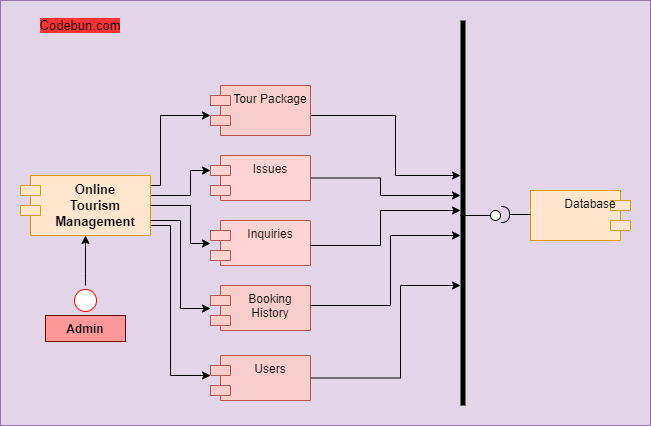
Component diagram for Online Tourism Management Project
In an Online Tourism Management system, the connected components by lines represent relationships within the systems. In the diagram, it can be seen that there are components namely product, order, customer, and account. The component diagram below shows the components of the Online Tourism Management System.
It shows how the customer component connects to the other components while using the system. Everything from the account details to product booking to payment flow can be seen in the component diagram.
Users can view all the packages according to the location or types of holidays and adventures. Users can check the price or select any holiday package according to the requirement. The online tourism management system will take responsibility for all the needful things about the customer requirement.
A centralized admin can manage all the actors of the application like tour packages, users, inquiries, etc.
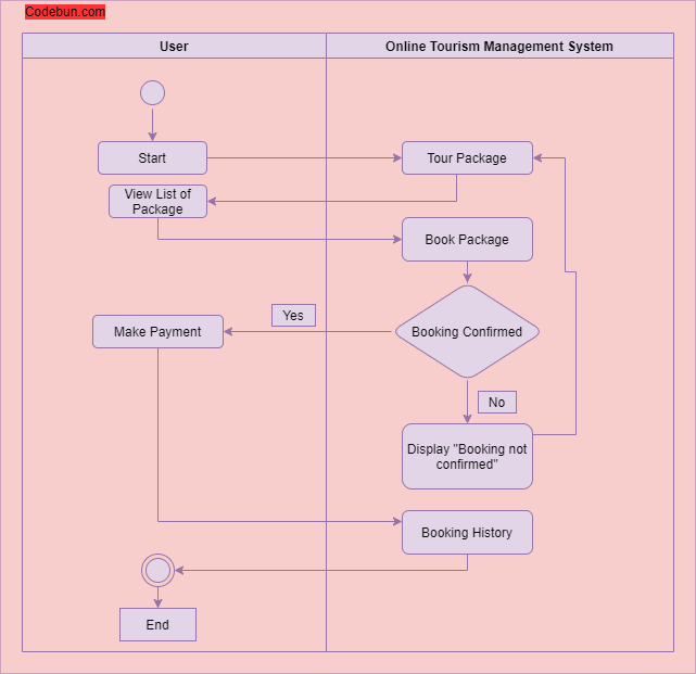
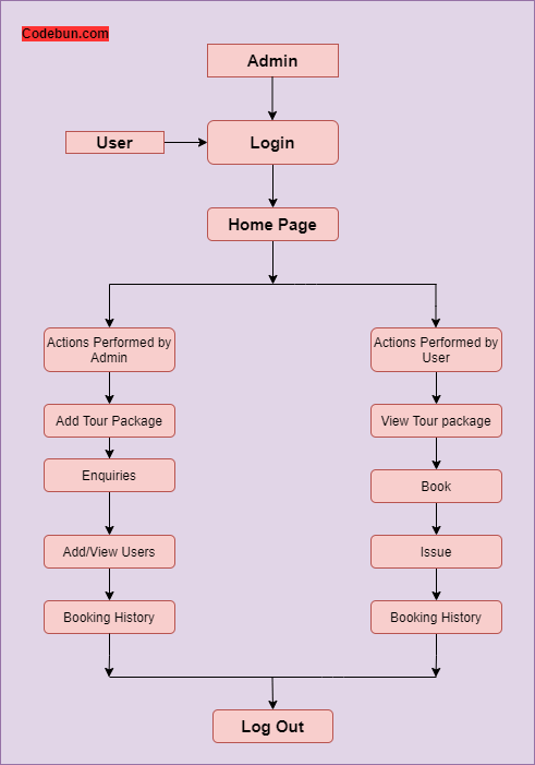
Activity diagram for Online Tourism Management Project
Activity diagrams in UML display the functionalities of various activities and flow in management processes and software systems. The flow in the activity diagram can be sequential, branched, or concurrent.
Admin can view the list of users. Admin can manage the category of packages and can update all package detail. Admin can view booking history and detail. Admin can manage inquiries, issues, payments, and transactions.
Online customers can browse or search packages, view specific packages, view them, book, and checkout. Users can view booking history at any time. Users can make payments for the booking and view the payment history.
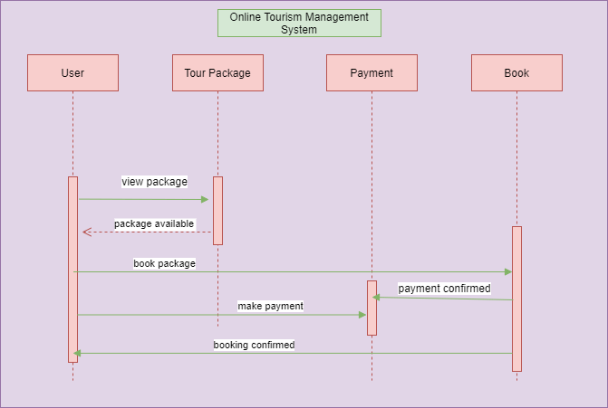
Sequence diagram for Online Tourism Management Project
Sequence diagrams in UML are used to better understand how tasks within a project will function, overlap, and move between objects or components. Sequence diagrams display step-by-step interactions between objects and the order in which those interactions occur.
Users can log in and register in the application at any time from anywhere and check their booking history also can make a new booking. Users can search for packages, view the price of a selected package, book the package, and make payments for the booking. As soon as the payment is confirmed, the user’s booking will be confirmed.
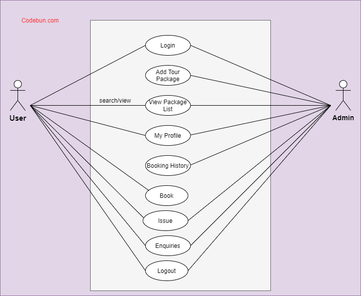
Use Case Diagram for Online Tourism Management Project
A UML use case diagram can create a broad, high-level view of the relationship between use cases, actors involved, and systems being performed.
As you can see from the examples below, use cases are represented by oval shapes, and the lines then show at which point an actor/user participates and interacts with their corresponding use case. You can see where each actor is involved within the entire process (and where they’re excluded).
Here, Admin will have the access to Add/Remove packages, answer inquiries, etc. Whereas, Users can view package lists, make inquiries, make payments, book packages, etc.
DFD Diagram for Online Tourism Management Project
A DFD maps out the flow of information for any process or system. It gives a basic overview of the whole system or process being analyzed. It shows the system with its relationship to external entities. Here, we can see how a system’s users and process flow work.
Initially, Admin and User must be logged in to the system. Upon logging in, both Admin and User will land on the home page where they can manage their profiles, view products, check prices of products, view cart, etc.
Admin manages the booking history, which is the bookings made by the users. Users can also view their bookings and payment confirmation on the system.
Click here to get the source code

Recent Post
Jsp and servlet project configuration tutorial, how to solve error dependencies.dependency.version’ for mysql:mysql-connector-java:jar is missing in pom.xml, atm management backend restapi project in spring boot, jpa, mysql, postman with source code, home service booking project in spring boot, hibernate, jpa and jsp with source code, ecommerce project in reactjs and spring boot using jpa, jwt, mysql, restapi, postman, current request is not a multipart request in spring boot and reactjs, submit form data with image or file in spring boot, reactjs and postman, college management project in spring boot and hibernate with source code, home loan management in reactjs and spring boot with source code, blog management project in reactjs and spring boot with source code.
- [email protected]
- +91 8827363777
- Who We Are?
- Services And Plan
- Privacy Policy
- Terms And Conditions
- Java program
- Selenium Tutorial
- Selenium Web Driver With Java
- Selenium Web Driver With C#
- Katalon studio
- Puppeteer and Jest

Use Case Diagram for Travel Reservation System
You may also like.

Create beautiful designs on-the-fly
No credit card required. No contracts to cancel. No downloads. No hidden costs.
©2024 by Visual Paradigm. All rights reserved.
- Terms of Service
- Privacy Policy
- Security Overview

Bold Travel Business Use Case
Compare business roles and more by customizing this bold travel business use case template.
- Design style modern
- Colors light
- Size Letter (11 x 8.5 in)
- File type PNG, PDF, PowerPoint
Explore more
Chapter 5. UML & Requirement Diagram
Use case diagram notations guide.
- How to draw a Use Case Diagram in UML
- Entering meeting nodes for Use Case
- How to draw a Class Diagram in UML
- How to draw a Sequence Diagram in UML
- How to animate a Sequence Diagram
- How to draw a Communication Diagram in UML
- How to draw a State Machine Diagram in UML
- How to draw a Activity Diagram in UML
- Splitting a control flow in Activity Diagram
- How to animate an Activity Diagram
- How to draw a Component Diagram in UML
- How to draw a Deployment Diagram in UML
- How to draw a Package Diagram in UML
- How to draw a Object Diagram in UML
- How to draw a Composite Structure Diagram in UML
- How to draw a Timing Diagram in UML
- How to draw a Interaction Overview Diagram in UML
- How to draw a Requirement Diagram
- Customizing requirement types
- Managing requirements with Requirement List
- How to create CRC Card Diagram
- Chapter 5. UML & Requirement Diagram
- 1. Use Case Diagram
Use case diagram is a kind of UML diagram . Here is a list of Unified Modeling Language (UML) notations supported in a UML use case diagram:
A use case represents a user goal that can be achieved by accessing the system or software application. In Visual Paradigm , you can make use of the sub-diagram feature to describe the interaction between user and system within a use case by creating a sub-sequence diagram under a use case. You can also describe the use case scenario using the Flow of Events editor.
OMG UML Specification
What is a use case in UML? According to the OMG Unified Modeling Language (OMG UML) specification (UML Superstructure Specification version 2.4.1, page 606), use case is:
Association

Actor and use case can be associated to indicate that the actor participates in that use case. Therefore, an association correspond to a sequence of actions between the actor and use case in achieving the use case.
What is an association in UML? According to the OMG Unified Modeling Language (OMG UML) specification (UML Superstructure Specification version 2.4.1, page 36), association is:
Actors are the entities that interact with a system. Although in most cases, actors are used to represent the users of system, actors can actually be anything that needs to exchange information with the system. So, an actor may be people, computer hardware, other systems, etc.
Note that actor represents a role that a user can play but not a specific user. So, in a hospital information system, you may have doctor and patient as actors but not Dr. John, Mrs. Brown as actors.
What is an actor in UML? According to the OMG Unified Modeling Language (OMG UML) specification (UML Superstructure Specification version 2.4.1), actor is:

The scope of a system can be represented by a system (shape), or sometimes known as a system boundary. The use cases of the system are placed inside the system shape, while the actor who interact with the system are put outside the system. The use cases in the system make up the total requirements of the system.
What is a system in UML? According to the OMG Unified Modeling Language (OMG UML) specification (UML Superstructure Specification version 2.4.1, page 608), system is:

An include relationship specifies how the behavior for the inclusion use case is inserted into the behavior defined for the base use case.
What is an include in UML? According to the OMG Unified Modeling Language (OMG UML) specification (UML Superstructure Specification version 2.4.1, page 604), include is:

An extend relationship specifies how the behavior of the extension use case can be inserted into the behavior defined for the base use case.
What is an extend in UML? According to the OMG Unified Modeling Language (OMG UML) specification (UML Superstructure Specification version 2.4.1, page 601), extend is:

A dependency relationship represents that a model element relies on another model element for specification and/or implementation.
What is a dependency in UML? According to the OMG Unified Modeling Language (OMG UML) specification (UML Superstructure Specification version 2.4.1, page 61), dependency is:
Generalization

A generalization relationship is used to represent inheritance relationship between model elements of same type. The more specific model element share the same specification with. the more general the model element but carries more details in extra.
What is a generalization in UML? According to the OMG Unified Modeling Language (OMG UML) specification (UML Superstructure Specification version 2.4.1, page 70), generalization is:
Realization

A realization is a relationship between a specification and its implementation.
What is a realization in UML? According to the OMG Unified Modeling Language (OMG UML) specification (UML Superstructure Specification version 2.4.1, page 131), realization is:
Collaboration

What is a collaboration in UML? According to the OMG Unified Modeling Language (OMG UML) specification (UML Superstructure Specification version 2.4.1, page 174), collaboration is:
IMAGES
VIDEO
COMMENTS
A UML (Unified Modeling Language) use case diagram is a visual representation of the interactions between actors (users or external systems) and a system under consideration. It depicts the functionality or behavior of a system from the user's perspective. Use case diagrams capture the functional requirements of a system and help to identify ...
Download scientific diagram | Use Case diagram of the tourist guide application. from publication: Integration of SOA and cloud computing in RM-ODP | The objective of ODP is according to ITU-T ...
Identify what is required from the system to achieve these goals. Step 4: Structure the use cases. Include in the description for each use case the basic course of events that will happen when a user performs a certain action. It should describe what the user does and how the system responds.
New Mobile Tourist Guide Use Case [classic] by avinash . Edit this Template. Use Creately's easy online diagram editor to edit this diagram, collaborate with others and export results to multiple image formats. Edit this Template Close. You can easily edit this template using Creately. You can export it in multiple formats like JPEG, PNG and ...
3.2.1 visitor Use Case Use case: Show tourism guide Diagram: Showtouris mguide visitor 15 DOC V 1.0 TGS DOCUMENTATION SE4 Description Where the tourist can see the various types of tourist attractions and view the det ails of these landmarks from the pictures of the landmarks in addition to the area where there is a tourist teacher and other ...
This travel reservation use case template can help you: - Organize the details of your system's users (also known as actors). - Map out users' interactions with a travel reservation system. - Access the UML shape libraries. Open this template to view a detailed example of a travel reservation use case diagram that you can customize to your use case.
A use case diagram is a graphical representation used in use case modeling to visualize and communicate these interactions and relationships. In a use case diagram, you'll typically see actors represented as stick figures, and the use cases (specific functionalities or features) as ovals or rectangles. Lines and arrows connect the actors to ...
Benefits of creating this diagram. Creating a use case diagram for a Travel Planning System has several benefits. Firstly, it helps to identify the various features and functionalities that the system should have, based on the needs of the users. By breaking down the system into smaller use cases, it becomes easier to understand the different ...
UML is the modeling toolkit that you can use to build your diagrams. Use cases are represented with a labeled oval shape. Stick figures represent actors in the process, and the actor's participation in the system is modeled with a line between the actor and use case. To depict the system boundary, draw a box around the use case itself.
This Travel Agency Use Case Diagram depicts possible interactions between a user or customer and a system. Use case diagrams, previously only used in computer programming, have gained popularity in the retail and customer service industries to explain how customers interact with a business. While they are still primarily used in computer programming and other technical fields, case diagrams ...
A UML (Unified Modeling Language) use case diagram is a graphical representation of the interactions between actors (users) and a system to achieve specific goals or tasks. It provides a high-level view of the system's functionality without delving into the internal details of the system's implementation.
A Use Case Diagram is a vital tool in system design, it provides a visual representation of how users interact with a system. It serves as a blueprint for understanding the functional requirements of a system from a user's perspective, aiding in the communication between stakeholders and guiding the development process.
The visitors may also use Smart Tourist Guide App instead of booking a professional guide man, and use this app for ... Fig 4.1 Use Case Diagram 38 Fig 4.3 Sequence Diagram 39
Posted By freeproject on July 24, 2017. This Use Case Diagram is a graphic depiction of the interactions among the elements of Tourism Management System. It represents the methodology used in system analysis to identify, clarify, and organize system requirements of Tourism Management System. The main actors of Tourism Management System in this ...
Use Case Diagram for Online Tourism Management Project. A UML use case diagram can create a broad, high-level view of the relationship between use cases, actors involved, and systems being performed. As you can see from the examples below, use cases are represented by oval shapes, and the lines then show at which point an actor/user ...
The Travel Booking Use Case Diagram outlines the different functionalities of a travel booking system. The first use case is to search for travel. This involves allowing customers to search for travel options, such as flights, hotels, and rental cars, based on their preferred destinations, dates, and other criteria.Customers can also filter their search results based on price, location, and ...
A use-case diagram is a simple way of presenting an overview of a system's requirements. ... A slice based on the basic flow is guaranteed to travel through the entire concept from end-to-end as it will be the most straightforward way for the user to achieve their goal. ... Use-Case 2.0 is free and offered to the public in this guide. Use ...
Designed by @Melinda Doering. Use Case Diagram for Travel Reservation System. A use case diagram example was developed for Travel Reservation System. Use this design as a use case example for teaching. The design can also be customized as a use case template, with Visual Paradigm's use case tool. Edit this Design.
Portrait. Process. Travel. Create the perfect use case diagram for your organization with this Bold Travel Business Use Case Template. Choose a vibrant color palette, apply neat illustrated icons, and use a modern font for an impressive design. Search Venngage for more eye-catching use case templates.
Use Case. A use case represents a user goal that can be achieved by accessing the system or software application. In Visual Paradigm, you can make use of the sub-diagram feature to describe the interaction between user and system within a use case by creating a sub-sequence diagram under a use case.You can also describe the use case scenario using the Flow of Events editor.
Academic Year. Description: This is a Use Case Diagram of Tourism management system. Preview the document. Uploaded on 07/11/2021. Rahid50🇧🇩5 documents. Recently viewed documents. Get ready for your exams with the best study resources. Sign up to Docsity to download documents and test yourself with our Quizzes.