Information
- 520: Long delay, Instantaneous - LSI (Long delay, Short delay, Instantaneous) - LSIG (Long delay, Short delay, Instantaneous, Ground Fault Trip)

Related Articles
- Number of Views 38
- Number of Views 8
- Number of Views 1
- Number of Views 12
- Number of Views 21
- eaton Manuals
eaton 520 Manuals

Eaton 520 Instructions Manual (40 pages)
Table of contents.
- Table of Contents 1
1 General Description of Digitrip Trip Units
- Protection 5
- Mode of Trip and Status Information 5
- Installation of the Trip Unit 5
- Rating Plug Installation 5
- Trip Unit/Rating Plug Removal 6
- Plexiglass Cover 7
- (520M & 520MC Models Only) 7
- Auxiliary Power 7
- Ground Alarm 7
- Ground Fault Trip 7
- Ground Fault Alarm 7
- High Load Alarm 7
- Display Feature (520M and 520MC Only) 8
- Standards 8
2 General Description of Magnum Circuit Breakers
- Low Energy Trip Actuator 9
- Residual Sensing 10
- Source Ground Sensing 10
- Zero Sequence Sensing 10
- Multiple Source/Multiple Ground 10
- Ground Fault Settings 11
- Current Sensors (Magnum Frames Less than or Equal to 3200A) 11
- Current Sensors (Magnum Frames Greater than 3200A) 11
3 Principles of Operation
- (Current Sensor Ratings and Rating Plugs) 11
- Trip and Operation Indicators 16
- Making Current Release 16
- Zone Interlocking (520 Family Only) 16
4 Protection Settings
- Long Delay Current Setting 21
- Long Delay Time Setting 22
- Short Delay Current Setting 22
- Short Delay Time Setting 22
- Instantaneous Current Setting 22
- Ground Fault Current Setting 23
- Ground Fault Time Delay Setting 23
- Breaker Interface Module (BIM) 23
- Remote Master Computer 24
- INCOM Network Interconnections 24
5 Test Procedures
- When to Test 25
- Field Test Kit 25
- Description of Handheld Test Kit 26
- Test Procedure 26
- Currents 26
- Batteries 26
- Code Requirements 26
- Standards Requirements 26
- General Test Instructions 26
- Performance Testing for Ground Fault Trip Units - Primary Injection 27
- Battery Check 28
- Battery Installation and Removal 28

7 Frame Ratings
8 record keeping, 9 references.
- Magnum and Magnum DS Circuit Breakers 29
- Time-Current Curves 29
Appendix A Zone Interlocking Examples
Appendix b troubleshooting guide, appendix c typical breaker master conn. diagram, appendix d modbus translator wiring.
Advertisement

eaton 520 Operating Manual (42 pages)
- Table of Contents 4
- Digitrip Trip Unit 6
- Low-Energy Trip Actuator 6
- Catalog Number Referencing 6
- Protection 6
- Mode of Trip and Status Information 7
- Installation and Removal 11
- Trip Unit/Rating Plug Removal 11
- Plexiglass Cover 11
- Voltage Supply Input/Alarms 11
- Display Feature (Digitrip 520M Only) 12
- Standards 12
- Trip and Operation Indicators 12
- Making Current Release (MCR) 12
- High Instantaneous 13
- Diagnostics Indicator-Circuit Breaker/Trip Unit 14
- Ground Fault Protection 14
- Long Delay Settings 15
- Short Delay Settings 16
- Instantaneous Settings 16
- When to Test 21
- Functional Field Testing 21
- Functional Test Kit (Handheld) 21
- Test Procedure 21
- Ground (Earth) Fault Performance Testing 21
- Battery Check 22
- Battery Installation and Removal 22
- Section 6: Rating Plugs 23
- Arcflash Reduction Maintenance System™ Mode (ARMS) 25
- Maintenance Mode 25
- Maintenance Mode Current Setting 25
- Actuating Maintenance Mode 25
- Remote Indication of Maintenance Mode 25
- Tripping and Testing 25
- Section 8: Communication Adapter Modules (CAM) 25
- Time-Current Curves 26
- Curve Select 26
- Appendix A: Zone Interlocking Examples 27
- Appendix B: Troubleshooting 29
- Appendix C: Specifications 30
- Record Keeping 32
- Notes for Previous Page 36
- Notes for Pages 36 and 37 (Diagram Drawing Number 6D32424 - RF Frame) 39

Eaton 520 Instructional Leaflet (40 pages)
- Table of Contents 2
- Dtscripoinn Pagt 2
- List of Figures 3
- List of Tables 4
- Installation and Removal 8
- Plexiglass Cover 9
- Ground Alarm/Power Supply Module (520M/MC Models Only) . 9 Display Feature (520M and 520MC Only) 10
- Standards 10
- Low-Energy Trip Actuator 11
- Ground Fault Protection 11
- Current Sensors (Magnum Standard Frames) 17
- Current Sensors (Magnum Double-Wide Frames) 17
- Trip and Operation Indicators 17
- Making Current Release 17
- Zone Interlocking 17
- Long Delay Current Setting 22
- Long Delay Time Setting 23
- Short Delay Current Setting 23
- Short Delay Time Setting 23
- Instantaneous Current Setting 24
- Ground Fault Current Setting 24
- Ground Fault Time Delay Setting 24
- INCOM (Digitrip 520MC Models Only) 25
- When to Test 26
- Functional Field Testing 26
- Primary Injection 27
- Battery Check 29
- Battery Installation and Removal 29
- Section 7: Frame Ratings (Sensor Ratings and Rating Plugs) 30
- Section 8: Record Keeping 30
- Time-Current Curves 31
- Maintenance Mode Settings 32
- Arming Maintenance Mode 32
- Remote Indicator 32
- Choosing the Reduction Setting 32
- Tripping and Testing 32
- Appendix A: Zone Interlocking Examples 34
- Appendix B: Troubleshooting Guide 36
- Appendix C: Typical Breaker Master Connection Diagram 37
- Appendix D: Modbus Translator Wiring 38

Eaton 520 Instructions Manual (36 pages)
- General Description of Digitrip Trip Units 2
- Protection 4
- Mode of Trip and Status Information 4
- Installation and Removal 4
- Installation of the Trip Unit 4
- Rating Plug Installation 4
- Trip Unit/Rating Plug Removal 5
- Plexiglass Cover 6
- Ground Alarm/Power Supply Module (520M Models Only) 6
- Auxiliary Power 6
- Ground Alarm 6
- Display Feature (520M Family Only) 7
- Standards 7
- General Description of Magnum Circuit Breakers 7
- Low Energy Trip Actuator 8
- Ground Fault Protection 8
- Residual Sensing 9
- Source Ground Sensing 9
- Zero Sequence Sensing 9
- Multiple Source/Multiple Ground 9
- Ground Fault Settings 9
- Current Sensors (Magnum Frames Less than or Equal to 3200A) 10
- Current Sensors (Magnum Frames Greater than 3200A) 10
- Principles of Operation 10
- Trip and Operation Indicators 15
- Making Current Release 15
- Zone Interlocking (520 Family Only) 15
- Protection Settings 19
- Long Delay Current Setting 19
- Long Delay Time Setting 19
- Short Delay Current Setting 20
- Short Delay Time Setting 20
- Instantaneous Current Setting 20
- Ground Fault Current Setting 21
- Ground Fault Time Delay Setting 21
- Test Procedures 21
- When to Test 22
- Functional Field Testing 22
- Performance Testing for Ground Fault Trip Units 22
- Code Requirements 22
- Standards Requirements 22
- General Test Instructions 22
- Battery Check 23
- Battery Installation and Removal 24
- Frame Ratings (Sensor Ratings and Rating Plugs) 24
- Record Keeping 25
- References 25
- Magnum and Magnum DS Circuit Breakers 25
- Time-Current Curves 25
- Appendix A Zone Interlocking Examples 29
- Appendix B Troubleshooting Guide 31
- Appendix C Typical Breaker Master Connection Diagram 33
Related Products
- Eaton 50 VCP-TR16
- Eaton 50 VCP-T20
- Eaton 50 VCP-TR25
- Eaton 50 VCP-T25
- Eaton 50 VCP-T40
- Eaton 50 VCP-TR32
- Eaton 50 VCP-TR40
- Eaton Digitrip OPTIM 550 KEP3125T52
- Eaton Digitrip OPTIM 550 KEP3400T52
eaton Categories
Upload manual

IMAGES
VIDEO
COMMENTS
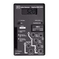
The Digitrip 520, 520M, and 520MC trip units may be applied on both 50 and 60 Hz systems. Figurt 1. Digiorip 520MC Trip Unio wioh Raoing Plug Auxiliary Power Module Input Rating Plug Protection Settings Cause of Trip LED INCOM Transmit LED Test Port (covered) Four- Character LCD All trip unit models are microprocessor-based AC protection devices
Page 13 Digitrip models 520, 520i; and 520M, 520Mi, Instructional Leaflet IL70C1037H05 520MC, 520MCi trip units for use only in Effective October 2009 Magnum and Magnum DS circuit breakers Source Black K1-2 Trip Digitrip 520 Actuator K1-3 with GF 10:1 K1-9 K1-8 K1-7 K1-6... Page 14 Insulation level: 0.6 kV, BIL 10 kV, full-wave Continuous ...
TRIP UNIT TO THE CIRCUIT BREAKER (See Figure 1.3). CLOSE THE RATING PLUG DOOR. CAUTION THE M4 SCREW SHOULD BE TIGHTENED ONLY UNTIL IT IS SNUG BECAUSE THERE IS NO STOP. DO NOT USE A LARGE SCREWDRIVER. A 1/8" (3mm) WIDE SCREWDRIVER BLADE IS ADEQUATE. 1.3.3 Trip Unit/Rating Plug Removal To remove the rating plug from the trip unit, make sure the
Control voltage is 120VAC or 230VAC or 24-48VDC or 125VDC. Check circuit breaker front cover for Trip Unit power requirements. A remote Stack Light, Annunciator Panel or other remote indication device can be connected to verify that the Digitrip is in the Maintenance Mode. Relay in GF Alarm/PS Module closes when Maintenance Mode is armed.
The trip units operate the basic overcurrent protection functions through current sensors mounted in the breaker, eliminating the need for external control power. When a breaker trips, an LED on the trip unit indicates the cause of the trip. Each model offers unique features: - 520: Protection only. - 520M: Current metering.
This instruction book specifically covers the application of Digitrip 520/520M units installed in Series NRX circuit breakers. The Digitrip trip units are circuit breaker subsystems that provide the protective functions of a circuit breaker. The primary function of the trip unit is circuit protection but some models offer additional features ...
The Digitrip 520 and 520M trip units may be applied on both 50 and 60 Hz systems. Page 7: Mode Of Trip And Status Information Operating Manual for Series NRX Instruction Leaflet IL01301051E Trip Units - Digitrip™ 520/520M effective September 2013 MNde Nf orip and soaous infNrmaoiNn On all models there are tri-colored light-emitting diodes ...
Trip units for use in magnum and magnum ds circuit breakers (40 pages) Circuit breakers Eaton Digitrip 520 Instructional Leaflet. Trip units for use only in magnum and magnum ds circuit breakers (40 pages) Industrial Electrical Eaton 75VCPW-VSR Instruction Book. ... white portion of the unit. OR MISINSTALLATION OF ITS PRODUCTS. 2.0 Maintenance ...
The Magnum Digitrip line of trip units consists of the 220, 520, and 520M for UL standards and models 220, 520 i, and 520Mi for IEC standards. Throughout this Instruc-tional Leaflet, the use of the term "DT20 family" refers to the 220, 520, 520 i, 520M, and 520M i units; the term "520 family" refers to only the 520, 520 i, 520M, and ...
3. The Long Delay Pickup Point (indicated by rapid flashing of Unit Status LED on the product) occurs at 110%, with a ±5% tolerance. The Instantaneous settings have conventional 100% ±10% at the pick up points. 4. With Zone Selective Interlocking enabled, max trip times w/o aux power are as follows: 3-phase fault 60 Hz 75ms 50 Hz 85ms
I.L. 70C1037H02 Page 4 The Digitrip 220, 520, and 520M trip units may be applied 1.2 Mode of Trip and Status Information on both 50 and 60 H z systems. On all DT20 units, a green light emitting diode (LED), labeled Status, blinks approximately once each second to Digitrip DT20 family of trip units are microprocessor- indicate that the trip unit ...
3. Total clearing times shown include the response times of the trip unit, the breaker opening and the interruption of the current. Clearing times are shown with auxiliary power present. 4. The Digitrip 520MC will light the Instantaneous LED for a Maintenance Mode Trip. 5. Nominal Reduction Values (Pickup)(Tolerance is ± 15%)
View online (40 pages) or download PDF (4 MB) Eaton IL70C1037H05: Magnum Digitrip 520, 520M, 520Mi, 520MC, and 520MCi trip units, IL70C1037H05: DigiTrip models 520, 520M and 520Mi, 520MC, 520MCi trip units for use only Magnum and Magnum DS circuit breaker Owner's manual • IL70C1037H05: Magnum Digitrip 520, 520M, 520Mi, 520MC, and 520MCi trip units, IL70C1037H05: DigiTrip models 520, 520M and ...
series-nrx-digitrip-520-operating-manual-il01301051e - Free download as PDF File (.pdf), Text File (.txt) or read online for free.
Control voltage is 120VAC or 230VAC or 24-48VDC or 125VDC. Check circuit breaker front cover for Trip Unit power requirements. A remote Stack Light, Annunciator Panel or other remote indication device can be connected to verify that the . Digitrip is in the Maintenance Mode. Relay in GF Alarm/PS Module closes when Maintenance Mode is armed.
The Power/Relay Module which is supplied with Digitrip RMS Trip Unit Models 610, 810, 910, 750, and 1050 is mounted in the left pole of the R-Frame Circuit Breaker as shown in Fig. 5. This module provides control power for operating the 4-digit display, communication cir-cuitry and it provides relay contact outputs.
downstream of the trip unit in Maintenance Mode. This is separate from the normal system protection setting of Instantaneous. The Maintenance Mode is located in the upper, white portion of the unit. 2.0 Maintenance Mode Settings. The Maintenance Mode Settings (labeled R5, R4, R3, R2, R1) provide the Arc Flash Reduction setting. R5 is the
Performance Testing of Digitrip Trip Units. 19. General. 19. Testing Using MS-2 Multiamp Tester. 19. Description of MS-2 Tester. 19. Primary Injection Testing. 20. Secondary Injection Testing. 21. 6 Battery. 23. General. 23. Battery Check. 23. Battery Installation and Removal. 23. 7 Frame Ratings (Sensor Ratings and Rating Plugs) 24.
This protection is functional even when Instantaneous is set to the OFF position. For Standard Frame rated 3200A and less of MDSC type, an additional Instantaneous Trip Module is provided in the breaker set to pickup at 160.0kA Instantaneous peak current level (85kA symmetrical RMS with 15% power factor).
Trip Units for use in Magnum and Magnum DS Circuit Breakers. Brand: Eaton | Category: Power distribution unit ... Zone Interlocking (520 Family Only) 16. 4 Protection Settings. 21. General. 21. Long Delay Current Setting. 21. Long Delay Time Setting. 22. Short Delay Current Setting. 22.
The Digitrip RMS 510 trip unit is designed for use in industrial circuit breaker environments where the ambient temperatures can range from -20 C to +85 C and rarely exceed 70 to 75 C. If, however. temperatures in the neighborhood of the trip unit do exceed this range, the trip unit performance may be degraded.
5. If Long Delay Thermal Memory is enabled, trip times may be shorter than indicated on this chart 6. The Long Delay Pickup Point (indicated by rapid flashing of Unit Status LED on the product) occurs at 110%, with a ±10% tolerance. ° ° ° Series NRX - T ype NF or RF Frame with Digitrip 520(LI) - Long DelayCurves Available Long Delay Time ...
eaton 520 Manuals. Manuals and User Guides for eaton 520. We have 3 eaton 520 manuals available for free PDF download: Operating Manual, Instructions Manual, Instructional Leaflet.