Wandering Atrial Pacemaker EKG Interpretation with Rhythm Strip
Ekg features, wandering atrial pacemaker ekg interpretation example.
This website is only for professional medical education. Contact your doctor for medical care. 2024 © MedEdu LLC. All Rights Reserved. Terms & Conditions | About Us | Privacy | Email Us

Wandering Atrial Pacemaker ECG Interpretation #312
Description.
- Rhythms are often named according to the origin of the electrical activity in the heart or the structure where the problem is occurring.
- Wandering Atrial Pacemaker is aptly named due to the electrical impulses causing the atrial activity are moving or wandering.
- These changes in the locus of stimulation affect the morphology of the P waves.
- In Wandering Atrial Pacemaker ECG, you must observe at least three different shaped P waves. No other changes in the tracing may be observed. The rhythm may or may not be regular.
- The PR interval is often affected, but does not have to be.
- The bottom line, is you must observe at least three different shaped P waves.
Practice Strip
Analyze this tracing using the five steps of rhythm analysis.
- Rhythm: Irregular
- P wave: Changing Shapes (3 or more)
- PR interval: Variable
- Interpretation: Wandering Atrial Pacemaker
Authors and Reviewers
- ECG heart rhythm modules: Thomas O'Brien.
- ECG monitor simulation developer: Steve Collmann
- 12 Lead Course: Dr. Michael Mazzini, MD .
- Spanish language ECG: Breena R. Taira, MD, MPH
- Medical review: Dr. Jonathan Keroes, MD
- Medical review: Dr. Pedro Azevedo, MD, Cardiology
- Last Update: 11/8/2021
- Electrocardiography for Healthcare Professionals, 6th Edition Kathryn Booth and Thomas O'Brien ISBN10: 1265013470, ISBN13: 9781265013479 McGraw Hill, 2023
- Rapid Interpretation of EKG's, Sixth Edition Dale Dublin Cover Publishing Company
- EKG Reference Guide EKG.Academy
- 12 Lead EKG for Nurses: Simple Steps to Interpret Rhythms, Arrhythmias, Blocks, Hypertrophy, Infarcts, & Cardiac Drugs Aaron Reed Create Space Independent Publishing
- Heart Sounds and Murmurs: A Practical Guide with Audio CD-ROM 3rd Edition Elsevier-Health Sciences Division Barbara A. Erickson, PhD, RN, CCRN
- The Virtual Cardiac Patient: A Multimedia Guide to Heart Sounds, Murmurs, EKG Jonathan Keroes, David Lieberman Publisher: Lippincott Williams & Wilkin) ISBN-10: 0781784425; ISBN-13: 978-0781784429
- Project Semilla, UCLA Emergency Medicine, EKG Training Breena R. Taira, MD, MPH
- ECG Reference Guide PracticalClinicalSkills.com
This website provides professional medical education. For medical care contact your doctor. 2024 ©MedEdu LLC. All Rights Reserved. Terms & Conditions | About Us | Privacy | Email Us | 1

Thursday, March 4, 2021
Blog #200 — wandering pacemaker (vs mat).
There is no clinical information is available for the ECG and 2-lead rhythm strip shown below in Figure-1 .
- HOW would you interpret this tracing?
- What treatment is likely to be needed?
====================================
Editorial Comment:
It is always challenging to interpret tracings without the benefit of clinical information. That said — this situation is common in clinical practice. My experience in this area derives from the 30 years during which I was charged with interpreting all ECGs ordered by 35 medical providers at a primary care clinic — as well periodic stints during which I interpreted hospital tracings without the benefit of any history.
- The challenge lies with having to decide which tracings in the “pile of ECGs to be interpreted” were those for which I needed to pull the medical chart ( or call the provider ) because of ECG findings of immediate potential concern.
- Obvious time constraints made it impossible to pull the chart for each ECG that I was given to read ( I’d never get anything else done if I did so ).
- I therefore became well versed in the skill of limiting the charts that I would pull to those patients whose ECGs showed findings I thought were important and potentially indicative of an acute situation that may have been overlooked.
=====================================
MY Thoughts on the ECG in Figure-1:
As always — systematic interpretation of any ECG should begin with assessing the cardiac rhythm. In general — lead II and lead V1 are the 2 best leads on a 12-lead tracing for assessing atrial activity — and we have the advantage in Figure-1 of a simultaneously-recorded 2-lead rhythm strip of both of these leads. By the Ps , Qs and 3R Approach:
- The rhythm in Figure-1 is clearly irregular .
- The QRS complex is narrow ( ie, not more than half a large box in duration = ≤0.10 second ) .
- The rate varies from 50 /minute — to just under 100 /minute.
- More than 1 P wave morphology is present . That said — P waves do appear to be related to neighboring QRS complexes, because the PR interval for the P wave shapes that we see remains constant ( See Figure-2 ) .
MY Thoughts on Figure-2:
There are 2 different P wave shapes in Figure-2 .
- The tracing begins with 3 sinus beats ( ie, RED arrows highlight 3 similar-looking upright-in-lead-II P waves — all with the same PR interval ) .
- P wave shape then changes for beats #4, 5 and 6 ( ie, BLUE arrows highlighting an almost isoelectric, if not negative P wave with fixed PR interval ) .
- The atrial focus then shifts back , with return to sinus P waves for beats #7, 8, 9 and 10 (ie, return of RED arrows highlighting similar-looking, upright P waves in lead II — albeit with variability in the R-R interval ).
- The rhythm in Figure-2 concludes with a slowing-down of the ventricular rate, as the 2nd atrial focus returns , in which the P wave is almost isoelectric (ie, BLUE arrows for beats #11 and 12 ).
BOTTOM LINE regarding Figure-1: The rhythm in Figure-2 is most consistent with a Wandering Atrial Pacemaker . This is because the change from one atrial site to the next occurs gradually over a period of several beats.
- PEARL: The reason it is uncommon ( if not rare ) in clinical practice to see a wandering atrial pacemaker — is that most providers do not pay long enough attention to beat-to-beat change in P wave morphology needed to identify gradual shift between at least 3 different atrial sites.
SUMMARY: Review of the KEY features of wandering atrial pacemaker is the theme below for our ECG Media Pearl #17 ( a 3:30 minute audio recording ).
- Written review of wandering pacemaker appears below in Figure-3 .
- Review of MAT is covered in our ECG Blog #199 .

Today’s E CG M edia P EARL # 17 ( 3:30 minutes Audio ) — What is a Wandering Atrial Pacemaker ( as opposed to MAT )?
A DDENDUM ( 3/4/2021 ) :
I received the following note from David Richley regarding today’s tracing: “I think I would use different terminology to describe this because to me the atrial pacemaker doesn’t so much ‘wander’ as ‘jump’. I would describe this as sinus arrhythmia with junctional escape rhythm at 60-65/minute every time the sinus node discharge rate slows to below that rate. I interpret the escape beats as junctional rather than atrial, because athough the P waves, ( which are initially negative in II, aVF and V4-V6 — and positive in aVR ) precede the QRS — the PR segment is very short, suggesting an AV nodal origin. However, we describe this phenomenon — I do agree that it’s likely to be completely benign.
MY Thoughts: Dave’s comment is one of the reasons why: i ) The diagnosis of wandering pacemaker requires clear demonstration of shift in the atrial pacemaker in at least 3 different sites. We only see 2 different sites here; and , ii ) The diagnosis of wandering atrial pacemaker is not common.
- It’s impossible to rule out Dave’s theory from the single tracing we have.
- That said — the BLUE arrow P wave site may or may not be of AV nodal origin ( you can see a similar, near-isoelectric P wave with short PR interval from a low atrial site ).
- I also considered the possibility of the BLUE arrow P waves representing junctional escape — but decided against it because the difference in R-R interval from what we see between beats #9-10 vs what we see between beats #10-11 is more than what I’d expect based on the cadence of rate variation I see from beats #7-10.
- Bottom Line: We both agree there is a shift in the pacemaker site in a rhythm that is likely to be benign. And, we both agree that additional monitoring would be needed for a definitive response. THANK YOU Dave!
No comments:
Post a comment.
We have a new app!
Take the Access library with you wherever you go—easy access to books, videos, images, podcasts, personalized features, and more.
Download the Access App here: iOS and Android . Learn more here!
- Remote Access
- Save figures into PowerPoint
- Download tables as PDFs

Wandering Atrial Pacemaker
- Download Chapter PDF
Disclaimer: These citations have been automatically generated based on the information we have and it may not be 100% accurate. Please consult the latest official manual style if you have any questions regarding the format accuracy.
Download citation file:
- Search Book
Jump to a Section
Key features, clinical presentation, diagnostic evaluation, ongoing management.
- Full Chapter
- Supplementary Content
ESSENTIALS OF DIAGNOSIS
Progressive cyclic variation in P-wave morphology
Heart rate 60–100 bpm
Variation of P-wave morphology, P-P interval, and P-R interval
GENERAL CONSIDERATIONS
This rhythm is benign
This rhythm and multifocal atrial tachycardia are similar except for heart rate
The other possible explanation is that there is significant respiratory sinus arrhythmia, with uncovering of latent foci of pacemaker activity
Usually, it is associated with underlying lung disease
In the elderly, it may be a manifestation of sick sinus syndrome
In the young and athletic heart, it may represent enhanced vagal tone
SYMPTOMS AND SIGNS
Usually causes no symptoms and is incidentally discovered
Occasional patient may feel skipped beats
PHYSICAL EXAM FINDINGS
Variable S 1
DIFFERENTIAL DIAGNOSIS
Multifocal atrial tachycardia (heart rate > 100 bpm)
Frequent premature atrial complexes and atrial bigeminy
LABORATORY TESTS
None specific
ELECTROCARDIOGRAPHY
ECG to document rhythm
CARDIOLOGY REFERRAL
Not required
MEDICATIONS
No specific treatment
Monitor and treat the underlying cause, such as sick sinus syndrome or lung disease
DIET AND ACTIVITY
No restrictions
General healthy lifestyle
Once a year if sinus node abnormality is suspected; otherwise when symptoms arise
COMPLICATIONS
May progress to sick sinus syndrome
This condition by itself is benign
PRACTICE GUIDELINES
Indications for pacemaker:
– If part of sick sinus syndrome
– If associated with documented symptomatic bradycardia
Sign in or create a free Access profile below to access even more exclusive content.
With an Access profile, you can save and manage favorites from your personal dashboard, complete case quizzes, review Q&A, and take these feature on the go with our Access app.
Pop-up div Successfully Displayed
This div only appears when the trigger link is hovered over. Otherwise it is hidden from view.
Please Wait
Practice Rhythm Strips
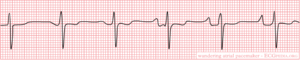
This ECG strip shows the classic changes of a wandering atrial pacemaker. Notice the slow, gradual transition of the P waves from upright to inverted. Longer strips show the transition occurring back and forth between the pacemakers. Notice that the QRS complexes and T waves are identical in this strip. There is no evidence of any aberrant conduction, as can sometimes occur with faster rates.
« Back to All

Pacemakers and Cardiac Devices
- Introduction to Cardiac Pacing and Devices: Pacemaker, ICD, CRT
- Components and construction of a pacemaker
- Basic cardiac pacing, pacemaker functions and settings
- Indications for pacemaker
Interpretation of Pacemaker ECG
- Assessment of Pacemaker Malfunction
Interpreting pacemaker ECGs
Assessing pacemaker function requires knowledge of the mode of pacing, and careful analysis of ECG tracings. Most modern devices are capable of transmitting ECG tracings continuously to cloud-based platforms, which enables the clinician to examine intracardiac ECGs at any time. However, most clinicians who encounter patients with pacemakers only have access to conventional surface ECGs. Being able to assess pacemaker function and perform troubleshooting should be considered a basic clinical skill.
Chapter content
Pacing activity may be visible or invisible, depending on e.g the type of pacemaker, intrinsic cardiac activity, etc. The cardinal manifestation of pacing on surface ECG is the stimulation artifact (Figure 1). In atrial pacing, the stimulation artifact precedes the P-wave. In ventricular pacing, the stimulation artifact precedes the QRS complex. Two artifacts are seen if both chambers are paced. The stimulation artifact is larger in unipolar pacing , as compared with bipolar pacing . The latter yields a discrete stimulation artifact, which may be visible in one or a few leads.

In addition to stimulation artifacts, ventricular pacing yields wide QRS complexes with LBBB morphology (i.e left bundle branch block appearance). This is explained by the fact that, as in LBBB, the left ventricle receives the depolarizing impulse from the right ventricle (where the pacemaker delivers the pulses). The depolarizing wave spreads outside the conduction system, which is considerably slower, as compared with impulse transmission within the conduction system (His-Purkinje network).
Assessing pacemaker function
The base rate is the lowest heart rate allowed by the pacemaker; intrinsic cardiac activity below the base rate will trigger pacing. The base rate is usually set to 60 beats/min. The base rate is virtually always >50 beats/min, meaning that any heart rate below 50 beats/min is most likely not paced. An intrinsic heart rate faster than the base rate should inhibit the pacemaker.
The appearance of the P-wave depends on where the atrial lead is fixed. Typically, the atrial lead is fixed next to the right atrial appendage, or atrial ceiling, which yields P-waves similar to those seen during normal sinus rhythm (i.e, positive P-wave in lead II). If the atrial lead is placed distally in the atrium, activation may proceed in the opposite direction, which results in negative (retrograde) P-waves in lead II.
QRS Complex
QRS morphology also depends on where the pacing stimulus is delivered. Typically, the lead tip is fixed apically in the right ventricle; activation starts in the right ventricle and spreads slowly to the left ventricle. As mentioned above, this is similar to the situation in left bundle branch block (LBBB) , which explains why paced QRS complexes are similar to the QRS morphology during LBBB.
Stimulation in other regions of the ventricle may result in a different QRS morphology. If the lead tip is fixed in the septum, the impulse may actually enter the conduction system (His-Purkinje network), which results in rapid impulse transmission and thus shorter QRS duration (as compared with apical pacing).
Because ventricular pacing results in abnormal depolarization, repolarization will also be abnormal, resulting in discordant ST-T segments (i.e the QRS complex and T-wave display opposite directions).
Below follows ECG tracings demonstrating these aspects.

ECG in biventricular pacing (CRT)
In biventricular pacing, stimulation occurs in both the right and left ventricle. With simultaneous atrial spacing, a total of three stimulation artifacts can be seen on surface ECG. Stimulation of the right and left ventricle need not occur exactly at the same time. The purpose of biventricular pacing is to synchronize ventricular contraction. This mode of pacing, referred to as cardiac resynchronization therapy (CRT), reduces morbidity and mortality in chronic systolic heart failure with a wide QRS complex. CRT does not, however, reduce morbidity and mortality in patients with QRS duration of less than 130 msec (1-4).
Fusion and pseudofusion
Fusion implies that the ventricle is simultaneously depolarized by the pacemaker stimulus and the intrinsic impulse passing through the His-Purkinje system. Fusion occurs if the pacemaker fails to sense intrinsic ventricular depolarization. It can also occur if the pacemaker senses the intrinsic depolarization too late.
Because the ventricle is activated both by the pacemaker stimulus and the intrinsic impulse, the QRS morphology resembles a fusion between a normal beat and a paced beat (Figure 8A).

Pseudofusion occurs in the same situations as fusion, but the depolarization from the pacemaker stimulus fails to spread through the myocardium (because it is refractory after conducting the intrinsic impulse). A stimulation artifact is seen, but the QRS complex is not affected (Figure 8B).
Acute myocardial infarction in a patients with pacemakers
Atrial pacing does not affect the QRS and ST-T segment. Thus, atrial pacing does not affect the interpretation of myocardial ischemia on ECG.
Ventricular pacing, however, results in a wide QRS complex and secondary ST-T-changes, which complicates detection of ischemia. As in left bundle branch block, these secondary ST-T changes may mask or mimic acute myocardial ischemia . There are three methods to approach this problem:
- Temporarily inactivate the pacemaker , if the patient has intrinsic cardiac activity. This potentially allows for examination of the ST-T segments during normal depolarization and repolarization. Note that switching off the pacemaker is a risky procedure, and cardiac memory may result in persisting ST-T changes even during normal ventricular depolarization. Cardiac T-wave memory implies that ST-T changes seen during pacing persist for a period after pacing is inactivated.
- Compare the current ECG tracing with previous tracings , in order to evaluate ST-T changes. Such changes may suggest ongoing ischemia.
- Use the Sgarbossa criteria , although they have not yet been validated for paced rhythms.
Pacemaker malfunction, including ECG interpretation , is discussed in the next chapter.
- Ruschitzka et al (N Engl J Med 2013; 369:1395-1405) – Cardiac-Resynchronization Therapy in Heart Failure with a Narrow QRS Complex
- Goldenberg et al (N Engl J Med 2014; 370:1694-1701) – Survival with Cardiac-Resynchronization Therapy in Mild Heart Failure
- Tang et al (N Engl J Med 2010; 363:2385-2395 – Cardiac-Resynchronization Therapy for Mild-to-Moderate Heart Failure
- Moss et al (N Engl J Med 2009; 361:1329-1338) – Cardiac-Resynchronization Therapy for the Prevention of Heart-Failure Events.
CONTINUE LEARNING
Evidence-based cardiovascular medicine., peer-reviewed courses., trusted by experts worldwide..
Join our newsletter and get a free ECG Pocket Guide

Start learning now
Wandering Pacemaker
When several pacemakers are competing, p-waves with different origins and thus configurations occur. The rhythm is slightly different from beat to beat.
note If the heart rate increases to above 100bpm, it is called Multifocal Atrial Tachycardia . Possible causes are hypoxia, COPD and medication such as digoxin.
Navigation menu


Pacemaker Rhythms – Normal Patterns
- Ed Burns and Robert Buttner
- Jul 7, 2022
Pacemaker Components
1. pulse generator.
- Power source
- Control circuitry
- Transmitter / Receiver
- Reed Switch (Magnet activated switch)
- Single or multiple
- Unipolar or bipolar
Pacemaker Classification
- Pacemakers are classified by the nature of their pacing mode.
- Classification follows pacemaker code developed by the North American Society of Pacing and Electrophysiology (NASPE) and the British Pacing and Electrophysiology Group (BPEG).
- The NASPE/BPEG Generic (NBG) Pacemaker Code was last revised in 2002, although many textbooks still use the previous version from 1987.
- The code is expressed as a series of up to five letters.
NBG Pacemaker Code (2002)

- Refers to chambers paced.
- Refers to the location where the pacemaker senses native cardiac electrical activity.
- Refers to pacemakers response to sensed native cardiac activity.
- T = Sensed activity results in triggering of paced activity
- I = Sensed activity results in inhibition of pacing activity
- Indicates ability for rate modulation designed to altered heart appropriately to meet physiological needs e.g. physical activity. Sensors may measure and respond to variables including vibration, respiration, or acid-base status.
- Allows indication of multiple stimulation sites within one anatomical area e.g. more than one pacing site within the atria or biatrial pacing

- Same as 2002 guidelines.
- Reflects the programming options available for pacemaker set-up or presence of rate modulation ability.
- Refers to presences of anti-tachydysrhythmia functions. Superseded by the NASPE/BPEG Defibrillator Code.
Common Pacing Modes
AAI – Atrial pacing and sensing
- If native atrial activity sensed then pacing is inhibited.
- If no native activity sensed for pre-determined time then atrial pacing initiated.
- Used in sinus node dysfunction with intact AV conduction.
- Also termed atrial demand mode.
VVI – Ventricle pacing and sensing
- Similar to AAI mode but involving ventricles instead of the atrium.
- Used in patients with chronic atrial impairment e.g. atrial fibrillation or flutter.
DDD – pacing and sensing the atria and ventricles
- Commonest pacing mode.
- Atrial pacing occurs if no native atrial activity for set time.
- Ventricular pacing occurs if no native ventricle activity for set time following atrial activity.
- Atrial channel function is suspend during a fixed periods following atrial and ventricular activity to prevent sensing ventricular activity or retrograde p waves as native atrial activity.
Magnet mode
- Applying a magnet to a pacemaker will initiate the magnet mode.
- This mode varies with pacemaker set-up and manufacturer.
- Usually initiates an asynchronous pacing mode – AOO, VOO, or DOO.
- Asynchronous modes deliver constant rate paced stimuli regardless of native rate of rhythm.
- In asynchronous ventricle pacing there is a risk of pacemaker-induced ventricular tachycardia.
- Note this differs from magnet application to an Implantable Cardioversion Defibrillator (ICD) which results in defibrillator deactivation.
Criteria for Pacemaker Insertion
- The 2002 American College of Cardiology, American Heart Association and North American Society for Pacing and Electrophysiology guidelines for implantation of cardiac pacemakers .
- ACC/AHA/HRS 2008 Guidelines for Device-Based Therapy of Cardiac Rhythm Abnormalities
Paced ECG – Electrocardiographic Features
The appearance of the ECG in a paced patient is dependent on the pacing mode used, placement of pacing leads, device pacing thresholds, and the presence of native electrical activity. Features of the paced ECG are: Pacing spikes
- Vertical spikes of short duration, usually 2 ms.
- May be difficult to see in all leads.
- Amplitude depends on position and type of lead.
- Bipolar leads result in a much smaller pacing spike than unipolar leads.
- Epicardially placed leads result in smaller pacing spikes than endocardially placed leads.
Atrial Pacing
- Pacing spike precedes the p wave.
- Morphology of p wave dependent of lead placement but may appear normal.
Ventricular Pacing
- Pacing spike precedes the QRS complex.
- Right ventricle pacing lead placement results in a QRS morphology similar to LBBB .
- Left epicardial pacing lead placement results in a QRS morphology similar to RBBB .
- ST segments and T waves should be discordant with the QRS complex i.e. the major terminal portion of the QRS complex is located on the opposite side of the baseline from the ST segment and T wave.
Dual Chamber Pacing
- Dependent on areas begin paced.
- May exhibit features of atrial pacing, ventricular pacing or both.
- Pacing spikes may precede only p wave, only QRS complex, or both.
The absence of paced complexes does not always mean pacemaker failure as it may reflect satisfactory native conduction. ECG Features

ECG Examples

A-V sequential pacing:
- Atrial and ventricular pacing spikes are visible before each QRS complex.
- There is 100% atrial capture — small P waves are seen following each atrial pacing spike.
- There is 100% ventricular capture — a QRS complex follows each ventricular pacing spike.
- QRS complexes are broad with a LBBB morphology, indicating the presence of a ventricular pacing electrode in the right ventricle.

- A-V sequential pacing — atrial and ventricular pacing spikes precede each QRS complex with 100% capture.

- Another example of A-V sequential pacing.

Ventricular paced rhythm:
- Ventricular pacing spikes precede each QRS complex (except perhaps complex #2 — although the QRS morphology in this complex is identical to the rest of the ECG, suggesting that this beat is also paced)
- No atrial pacing spikes are seen.
- The underlying native rhythm is probably coarse atrial fibrillation — there are several possible P waves visible in V1 but otherwise the atrial activity is chaotic.

- Ventricular pacing spikes precede most of the QRS complexes.
- The 6th and 7th beats are narrower, with a different morphology — these are non-paced (“capture”) beats, probably supraventricular in origin.
- There is a pacing spike superimposed on beat #6, but this does not appear to alter its morphology — i.e. no evidence of a fusion complex.

- Ventricular pacing spikes precede the QRS complexes, most of which exhibit LBBB morphology consistent with a RV pacing electrode.
- The 5th, 6th and 11th complexes are narrower with a different morphology — these are fusion beats produced when the ventricle is simultaneously activated by both paced and supraventricular (native) impulses. You can see how the pacing spike is shortened and the QRS duration narrowed by the co-incident native impulse.
- The 4th complex is probably a supraventricular capture beat , although there may still be some hybridisation with a pacing spike.

Atrially paced patients often have evidence of 1st degree AV block or Wenckebach conduction on their paced ECG that is not apparent on their baseline tracing.
This is because the sort of patients that require atrial pacing (e.g. post-op cardiac surgery) commonly have some degree of AV node dysfunction (e.g. due to age-related AV-nodal degeneration / their underlying cardiac condition / post-operative ischaemia / AV-nodal blocking drugs).
When these patients are paced at a faster rate than their AV node can handle, the AV node becomes “fatigued” resulting in 1st degree AV block or Wenckebach phenomenon on the paced ECG. This abnormality is not clinically important provided that the patient’s cardiac output is not compromised.

Atrial paced rhythm with 1st degree AV block:
- There are regular pacing spikes at 90 bpm.
- Each pacing spike is followed by a P wave, indicating 100% atrial capture.
- P waves are conducted to the ventricles with a prolonged PR interval (280 ms).

Atrial paced rhythm with Wenckebach conduction:
- There are regular atrial pacing spikes at 90 bpm; each one is followed by a small P wave indicating 100% atrial capture.
- However, not every P wave results in a QRS complex — the PR interval progressively lengthens, culminating in failure of AV conduction (“dropped QRS complexes”).
- There is a co-existent 2nd degree AV block with Mobitz I conduction (Wenckebach phenomenon).
- The Mobitz I is due to the patient being paced at a rate faster than his AV node can handle — at his own intrinsic rate of 50-60 bpm he had only a 1st degree AV block.
To find out the story behind this ECG, check out ECG Exigency 011 .
Pacemaker Puzzler
Can you work out what is going on in this ECG?

- There is an irregularly irregular rhythm with multiple atrial and ventricular pacing spikes.
- The majority of the QRS complexes are broad (120ms) and preceded by ventricular pacing spikes.
- The LBBB morphology is consistent with a ventricular pacing electrode located in the right ventricle.
The varying relationship between the atrial and ventricular pacing spikes is best understood by examining the lead II rhythm strip (below):
- Beat 1 is narrow — this appears to be a native ventricular complex triggered by an atrial pacing spike. This indicates that AV conduction is intact to some degree (i.e. 3rd degree AV block cannot be present).
- Beat 9 is broad with a completely different morphology and axis to the rest of the strip — this is a ventricular ectopic beat.
- Beats 3, 6, 8, 10 and 12 are preceded by both atrial and ventricular pacing spikes — sequential A-V pacing.
- Beats 2, 4, 5, 7 and 11 are preceded by ventricular pacing spikes only. The absence of atrial pacing spikes suggests that the pacemaker is responding to native supraventriclar impulses.
- Given the absence of discernible P waves and the very irregular rhythm, it is likely that the underlying native rhythm is atrial fibrillation.

- Atrial fibrillation with DDD pacing and occasional ventricular ectopics.
Related Topics
- Pacemaker essentials: Medmastery
- Pacemaker malfunction
- Left bundle branch block
- Right bundle branch block
- Sgarbossa Criteria
- Bernstein AD, Camm AJ, Fletcher RD, Gold RD, Rickards AF, Smyth NP, Spielman SR, Sutton R. The NASPE/BPEG generic pacemaker code for antibradyarrhythmia and adaptive-rate pacing and antitachyarrhythmia devices . Pacing Clin Electrophysiol. 1987 Jul;10(4 Pt 1):794-9.
- Bernstein AD, Daubert JC, Fletcher RD, Hayes DL, Lüderitz B, Reynolds DW, Schoenfeld MH, Sutton R. The revised NASPE/BPEG generic code for antibradycardia, adaptive-rate, and multisite pacing. North American Society of Pacing and Electrophysiology/British Pacing and Electrophysiology Group . Pacing Clin Electrophysiol. 2002 Feb;25(2):260-4
- Gregoratos G et al. ACC/AHA/NASPE 2002 guideline update for implantation of cardiac pacemakers and antiarrhythmia devices: summary article: a report of the American College of Cardiology/American Heart Association Task Force on Practice Guidelines (ACC/AHA/NASPE Committee to Update the 1998 Pacemaker Guidelines) . Circulation. 2002 Oct 15;106(16):2145-61
Advanced Reading
- Wiesbauer F, Kühn P. ECG Mastery: Yellow Belt online course. Understand ECG basics. Medmastery
- Wiesbauer F, Kühn P. ECG Mastery: Blue Belt online course : Become an ECG expert. Medmastery
- Kühn P, Houghton A. ECG Mastery: Black Belt Workshop . Advanced ECG interpretation. Medmastery
- Rawshani A. Clinical ECG Interpretation ECG Waves
- Smith SW. Dr Smith’s ECG blog .
- Zimmerman FH. ECG Core Curriculum . 2023
- Mattu A, Berberian J, Brady WJ. Emergency ECGs: Case-Based Review and Interpretations , 2022
- Straus DG, Schocken DD. Marriott’s Practical Electrocardiography 13e, 2021
- Brady WJ, Lipinski MJ et al. Electrocardiogram in Clinical Medicine . 1e, 2020
- Mattu A, Tabas JA, Brady WJ. Electrocardiography in Emergency, Acute, and Critical Care . 2e, 2019
- Hampton J, Adlam D. The ECG Made Practical 7e, 2019
- Kühn P, Lang C, Wiesbauer F. ECG Mastery: The Simplest Way to Learn the ECG . 2015
- Grauer K. ECG Pocket Brain (Expanded) 6e, 2014
- Surawicz B, Knilans T. Chou’s Electrocardiography in Clinical Practice: Adult and Pediatric 6e, 2008
- Chan TC. ECG in Emergency Medicine and Acute Care 1e, 2004
LITFL Further Reading
- ECG Library Basics – Waves, Intervals, Segments and Clinical Interpretation
- ECG A to Z by diagnosis – ECG interpretation in clinical context
- ECG Exigency and Cardiovascular Curveball – ECG Clinical Cases
- 100 ECG Quiz – Self-assessment tool for examination practice
- ECG Reference SITES and BOOKS – the best of the rest
ECG LIBRARY

Emergency Physician in Prehospital and Retrieval Medicine in Sydney, Australia. He has a passion for ECG interpretation and medical education | ECG Library |

Robert Buttner
MBBS (UWA) CCPU (RCE, Biliary, DVT, E-FAST, AAA) Adult/Paediatric Emergency Medicine Advanced Trainee in Melbourne, Australia. Special interests in diagnostic and procedural ultrasound, medical education, and ECG interpretation. Editor-in-chief of the LITFL ECG Library . Twitter: @rob_buttner
One comment
[…] Review on pacemaker modes at: https://litfl.com/pacemaker-rhythms-normal-patterns/ […]
Leave a Reply Cancel reply
This site uses Akismet to reduce spam. Learn how your comment data is processed .
Privacy Overview
IMAGES
VIDEO
COMMENTS
This article is a guide for interpreting abnormal Wandering Atrial Pacemaker EKGs, including qualifying criteria and a sample EKG rhythnm strip. Wandering atrial pacemaker is an arrhythmia originating in shifting pacemaker sites from the SA node to the atria and back to the SA node. On an ECG, the p-waves reflect the pacemaker shifts by shape variations. The PRI interval may vary from one beat ...
Wandering Atrial Pacemaker (WAP) is a cardiac rhythm disorder that causes irregular and variable heartbeats. Learn the Heart - Healio provides a comprehensive ECG review of this condition ...
Wandering Atrial Pacemaker Rhythm Strip Features. Rate: Normal (60-100 bpm) Rhythm: May be irregular. P Wave: Changing shape and size from beat to beat (at least three different forms) PR Interval: Variable. QRS: Normal (0.06-0.10 sec) The electrical impulses causing the atrial activity are moving or wandering.
Analysis. In Wandering Atrial Pacemaker ECG, you must observe at least three different shaped P waves. No other changes in the tracing may be observed. The rhythm may or may not be regular. The PR interval is often affected, but does not have to be. The bottom line, is you must observe at least three different shaped P waves.
A wandering atrial pacemaker is usually found with an electrocardiogram ( EKG or ECG). It's a test that lets your doctor see a record of the electrical signals in your heart. If the irregular ...
MY Thoughts on the ECG in Figure-1: As always — systematic interpretation of any ECG should begin with assessing the cardiac rhythm. In general — lead II and lead V1 are the 2 best leads on a 12-lead tracing for assessing atrial activity — and we have the advantage in Figure-1 of a simultaneously-recorded 2-lead rhythm strip of both of ...
Wandering atrial pacemaker (WAP) is an atrial rhythm where the pacemaking activity of the heart originates from different locations within the atria. This is different from normal pacemaking activity, where the sinoatrial node (SA node) is responsible for each heartbeat and keeps a steady rate and rhythm. Causes of wandering atrial pacemaker are unclear, but there may be factors leading to its ...
An atrial arrhythmia that occurs when the natural cardiac pacemaker site shifts between the sinoatrial node (SA node), the atria, and/or the atrioventricular...
Diagnose Wandering Atrial Pacemaker with confidence! This video explores the shifting pacemaker sites and the resulting "multifocal P waves" observed on an E...
This rhythm and multifocal atrial tachycardia are similar except for heart rate. The other possible explanation is that there is significant respiratory sinus arrhythmia, with uncovering of latent foci of pacemaker activity. Usually, it is associated with underlying lung disease. In the elderly, it may be a manifestation of sick sinus syndrome.
Name that strip: Answers. Rhythm: Irregular. Rate: 60 beats/minute. P waves: Vary in size and shape. PR interval: 0.08 to 0.12 second. QRS complex: 0.04 to 0.08 second. Interpretation: Wandering atrial pacemaker. Wandering atrial pacemaker (WAP) occurs when the pacemaker site shifts back and forth between the sinus node and ectopic atrial sites ...
Practice Rhythm Strips. This ECG strip shows the classic changes of a wandering atrial pacemaker. Notice the slow, gradual transition of the P waves from upright to inverted. Longer strips show the transition occurring back and forth between the pacemakers. Notice that the QRS complexes and T waves are identical in this strip.
The base rate is the lowest heart rate allowed by the pacemaker; intrinsic cardiac activity below the base rate will trigger pacing. The base rate is usually set to 60 beats/min. The base rate is virtually always >50 beats/min, meaning that any heart rate below 50 beats/min is most likely not paced. An intrinsic heart rate faster than the base ...
For atrial fibrillation, electrical cardioversion is most successful if used. During first 48 hours after onset arrhythmia. In a patient with wandering pacemaker the ECG strip will show. slight irregularity because sites of impulse initiation vary. Study with Quizlet and memorize flashcards containing terms like The hallmark of PAC is, In ...
Wandering Pacemaker. Wandering pacemaker. Every p-wave is different and thus has a different origin. When several pacemakers are competing, p-waves with different origins and thus configurations occur. The rhythm is slightly different from beat to beat. note If the heart rate increases to above 100bpm, it is called Multifocal Atrial Tachycardia.
Wandering Atrial Pacemaker (WAP) SPECIAL NOTE: Usually, you will have some NORMAL P wave configurations and two (or more) other Pwave configurations with a WAP (such as shown below). However, to call the EKG a WAP, you must see THREE different P wave configurations in your EKG Strip.Ectopic means 'other' sites (than SA node).
If the rate is more than 100, this would be considered Multifocal Atrial Tachycardia (MAT). It is possible for a wandering atrial pacemaker to occur more often in the young and among athletes. The cause usually stems from an augmented vagal tone. An increase in the vagal tone causes a slower heart rate and allows the AV node or the atria to ...
This results in at least three different P wave morphologies, and often the PR interval may vary due to this. If the heart rate is less than 100 BPM we call this a wandering atrial pacemaker, or WAP. If it's greater than 100 BPM we call it a multifocal atrial tachycardia, or MAT for short.
The pacemaker is activated and delivers a stimulus only when the intrinsic ventricular rate falls below a predetermined lower limit; pacemaker activity is suppressed when …. ECG tutorial: Basic principles of ECG analysis. … block; multifocal atrial rhythm (wandering atrial pacemaker) when the rate is <100 or multifocal atrial tachycardia ...
Multifocal Atrial Tachycardia (MAT) Overview. A rapid, irregular atrial rhythm arising from multiple ectopic foci within the atria. Most commonly seen in patients with severe COPD or congestive heart failure. It is typically a transitional rhythm between frequent premature atrial complexes (PACs) and atrial flutter / fibrillation.
The appearance of the ECG in a paced patient is dependent on the pacing mode used, placement of pacing leads, device pacing thresholds, and the presence of native electrical activity. Features of the paced ECG are: Pacing spikes. Vertical spikes of short duration, usually 2 ms. May be difficult to see in all leads.
Wandering atrial pacemaker (WAP) is a benign atrial arrhythmia observed in elderly patients suffering from obstructive pulmonary diseases that result from an ischemic heart. This report discusses WAP as observed in a patient who suffered an electrical injury. Keywords: wandering atrial pacemaker, voltage, electrical injury, arrhythmia, ampere.