The #1 website for NICET Practice Tests, NICET study guides, Fire Alarm Code Knowledge, and General Fire Alarm Topics. We have up to date information on the newest fire alarm trends such as fire service access elevators, mass notification, voice intelligibility, occupant evacuation elevators and two-way communication for Areas of Refuge. Topics also include fire alarm system programming and technical tips. Learn how to build the best ground fault meter with step by step instructions.
- NICET Exam Practice Test
- Bluebeam for Fire Alarm Design
- Occupancy FA Requirements
- 520 HZ Low Frequency Audible Tone
- Industry Links
- Conduit Bending

Tuesday, March 24, 2015

Elevator Shunt Trip Requirements and Codes
Elevator shunt trip explained, what specific codes or standards address elevator shunt trip.
- Elevator may react erratically due to water shorting out controls
- Water on the elevator braking system
- Risk of Shock or Electrocution
Can the Elevator Shunt Trip Activation be Delayed?
Shunt trip control circuits to be monitored for operating voltage , what is the requirement for shunt trip breaker location, resetting a shunt trip breaker.
When is the shut trip breaker tested

- Fire Engineering Training
Elevators: Power Shunt Trip
Greg Havel discusses how an elevator’s power shunt trip, which is activated before automatic fire sprinklers discharge, could affect firefighting operations and how firefighters can deal with them.
Article and photos by Gregory Havel
The ASME and NFPA standards and codes consider the occupants of an elevator car that is stopped between floors or that is evacuated at the nearest floor level to be at less risk than they would be if the elevator continued to operate during fire sprinkler discharge.
3. Arriving firefighters may initiate Phase II Emergency In-car Operation by using a key and pressing buttons inside the elevator car to close and open doors and to move the car between floors. Photo 1 shows a typical lobby elevator control panel with the key switch to select firefighter operation. Photo 2 shows a typical elevator car control panel, with the firefighter key switch and indicator lights in the red panel in the center and operating instructions in red directly above. In this way, firefighters can quickly move equipment to upper floors nearer the location of the fire and evacuate persons who are unable to self-evacuate using stairways.
4. If smoke is present at the top of the elevator hoistway or in the machine room, the smoke detector will activate a circuit in the elevator controller. This will cause the red firefighter helmet indicator light on the control panel (see photos) to begin to flash, indicating that smoke and fire are near the elevator machine or in the hoistway and that a power shunt trip is possible. The instructions on the panel in Photo 2 state, “WHEN [fire helmet] FLASHES, EXIT ELEVATOR.” Firefighters at this time have the choice of manually opening the elevator doors at the nearest floor and exiting the elevator or attempting to return the elevator car to the primary recall floor with the risk of becoming trapped in the elevator between floors when the power shunt trip breaker operates.
5. When significant heat is present at the top of the elevator hoistway or in the machine room, the heat detector near a sprinkler head will sense that sprinkler discharge is imminent and will cause the main elevator power to shunt trip without delay, without any action by the elevator controller. This power shunt trip breaker can only be reset manually in the elevator machine room. Disconnection of the elevator main power does not affect lights or communications with the elevator car, which are on separate circuits.
However, there are two (rare) scenarios in which firefighters or other building occupants could become trapped by a power shunt trip:
- A very slow elevator, or one with a great distance to travel, with a fast-moving fire in or near the elevator machine room. In this instance, the elevator does not have time to complete Phase I recall before the power shunt trip.
- A large-scale incident in a multistory residential building occupied by many persons who are not capable of self-evacuating by way of stairs, which could result in firefighters using the elevator on Phase II operation to the last possible moment to remove as many occupants as possible.
The author acknowledges the valued assistance with the research for this article by Brian Rausch PE, at the Wisconsin Elevator Safety Program of the Wisconsin Department of Commerce.

- Download this article as a PDF!
- More Construction Concerns
- More Building Construction
- More Fire Prevention and Protection
Subjects: Building construction for firefighters
Related Posts

Latest Fire Engineering News
Please check your spam folder and any email filters, in the event that the email gets blocked.

Stay informed about daily FireEngineering news, podcasts, training videos, webcasts, commentary, and exclusive articles about FireEngineering by signing up.
Unauthorized Request
Unauthorized activity detected.
All locations
Please select your country & language
Your country is not in the list?
Go to our international website:

Fusible Shunt Trip Switch and Multi-Unit Fusible Shunt Trip Panel
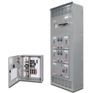
Mersen’s Fusible Shunt Trip Switch and corresponding Multi-Unit Fusible Shunt Trip Panels are UL Listed industrial control panels offering remote load-break disconnection capability to emergency circuits. Mersen offers over 90,000 configurable options of single unit shunt trip switches, which allows for optimal functionality to be built into a single compact panel. For last minute jobs, Mersen now stocks an offering of popular models for quick shipment. For larger buildings with banks of 2 or more elevators, Mersen now offers a panel with up to six elevator protection and control modules. This greatly reduces wiring, installation time, footprint and commissioning time. No matter what you are facing on the jobsite, Mersen has options to help you get your equipment on-site and running.
The right design for your application
For use in fire safety and elevator control
Mersen’s Fusible Shunt Trip Switch is an all-in-one solution that meets many different code requirements with the protection and safety in elevator shafts. According to NFPA 13, 8.14.5, sprinkler protection is required at the top and bottom of elevator shafts. With that being said, NFPA 13 requires the installation of sprinklers in the elevator machine room. Once a sprinkler system has been introduced to either the elevator shaft or elevator machine room, you are now installing these per the State-Adopted Elevator Code ANSI/ASME A17.1.
To summarize ASME A17.1, Safety Code for Elevators and Escalators, Rule 102.2 (c) (3) requires the shutdown of power to the elevator prior to the application of water in the elevator machine room and or hoistway.
The shutdown of power is accomplished by a shunt trip device in the elevator circuit. This reduces the risk of any potential electrical shock once the water is released into the system. This will also reduce the risk of any elevator car slippage once the cables and hoist system become saturated from the release of water. In addition to turning off the power, 2002 NFPA 72 6.15.4.4 (Fire Alarm Code) requires:
“Control circuits to shut down elevator power shall be monitored for the presence of operating voltage. Loss of voltage to the control circuit for the disconnecting means shall cause a supervisory signal to be indicated at the control unit and required remote annunciation.”
This is achieved with the Fire Monitoring Relay (FR Relay), a standard feature in Mersen’s Fusible Shunt Trip Device. In the event of a power loss, at which point a back up power supply is introduced to the system, you are now required to meet NEC Article 620.91 paragraph (C) emergency or standby power system. This is accomplished with a set of mechanical interlock auxiliary contacts which comes standard as 1-N/O and 1-N/C contact. The auxiliary contacts prevent the elevator from descending down and injuring any workers that could be working in the elevator shaft. This also allows the elevator to move to the next convenient location and open the doors to let any passengers out in the event of an emergency.
- Shunt Trip Switch – Allows for tripping of the main line power via remote signal
- Fused Switch – Provides high current-limitation and short circuit withstand
- Padlockable Handle – Allows panel to be locked with switch in the off position ensuring load side power isolation during servicing
Applicable Codes and Standards:
- NFPA 13, 8.14.5
- NFPA 72 6.15.4.4
- ANSI/ASME A17.1
- cUL US Listed
Capabilities
An array of available options allows for maximum functionality to be built into a single compact panel. Panels built for elevator applications feature control transformers (fusing both primary and secondary sides), a fire safety interface relay with a fire alarm voltage monitoring relay, and mechanically interlocked auxiliary contacts. Use of Mersen’s Amp-Trap 2000® AJT Class J fuses permits easy selective coordination, while providing the panel and its components with superior current limitation and the ability to withstand high fault conditions. AJT fuses provide added system reliability since no maintenance or periodic testing is required as with other electromechanical overcurrent devices.
Fusible Shunt Trip Switch
- Primary Voltage (208, 240, 480 or 600 VAC)
- Standard voltage monitoring relay.
- Fire safety relay for control interface (3PDT Relay, choice of Coil Voltage: 120 VAC, 24 VDC or 24VAC)
- Oil-tight key switch to test 2 position selector switch
- Oil-tight power enabled indicator light (choice of colors: red, green or white)
- Isolated neutral lug – 100%. Oversized 200% for excessive Non-Linear loads
- Multiple options for auxiliary contacts and alarm contacts for indication. Handle activated microswitch is available for operation under test conditions.
- NEMA 12, 3R, 4 or 4X enclosure available
- DC Shunt Trip Switch Version Available – Consult Factory
Multi-Unit Fusible Shunt Trip Switch Panel:
- Top or Bottom Feed, Main Fused Switch (400, 600A, or 800A) or Main Lug Only (MLO)
- Branch ratings of 30A, 60A, 100A, 200A, and 400A branch frame sizes available. Unit can accommodate up to (6) shunt trip switches of 200A or below, or up to (3) 400A units, or combinations thereof.
- Standard Two Form C Auxiliary contacts.
Design Guide
datasheets, operation and maintenance manual.

In order to enjoy this content, you need to help yourself to some cookies first! Please use the link below to update your preferences.
Privacy settings
Mersen Fusible Shunt Trip Switch Video
Mersen's Fusible Shunt Trip Switch is an all-in-one solution for use in fire safety and elevator controls. Our new video describes how a shunt trip switch operates to protect elevators, emergency systems, and more,
Mersen’s reputation for outstanding technical expertise, product quality, and engineered safety is the result of over a century of design and manufacturing knowledge, coupled with state-of the-art equipment in three ISO-9001 registered facilities. Each facility manufactures single and multilayer bus bars, as well as fully integrated solutions in which the laminated bus bar also serves as a platform for a multitude of discreet components.
42.823086316295, -70.887182028602
Our N.A. Design center
Newburyport
374 Merrimac Street 01950 MA United States

Compliance with the 2017 NEC for Elevator Controllers
Traditionally, the electrical system design engineer has given little attention to the elevator controller. In fact, an entire elevator system for a project is most often designed and specified by the architect who has little understanding of the electrical distribution system. Because of this, there is often a communications gap between the electrical system designer, whose design typically stops at the required elevator disconnecting means, and the architect who designs the elevator system. To address this issue, Code Making Panel (CMP) 12 of the National Electrical Code ® acted on several proposed changes to Article 620 during the revision cycle for the 2017 NEC that deal with the proper installation of elevator controllers.
The proposals resulted in adding new requirements in the 2017 NEC for:
- Marking the elevator controller short-circuit current rating (SCCR) by the elevator controller manufacturer.
- Reinforcing NEC 3 (B) and NEC 110.10 to require the elevator controller marked SCCR to be equal to or greater than the calculated and marked available short-circuit (fault) current at the elevator controller.
- Marking the available short-circuit (fault) current on the controller by the equipment installer.
This article will also discuss other Code requirements that include selective coordination for elevators that are supplied by emergency, legally required standby or critical operation power systems or multiple elevators supplied from a single feeder, and shunt tripping of elevators where the elevator equipment room and/or shaft has a fire suppression sprinkler system. Finally, typical installations and compliance with all these requirements will be discussed.
Equipment SCCR and short-circuit current marking requirements
The reason the NEC CMP 12 added these requirements, as shown in the panel statements, directly relates to the concern that elevator controllers can be installed in locations where the available fault current can be high and the inspector may not be able to clearly determine the SCCR of the elevator controller unless it is marked on the equipment. The panel further clarified that the marked SCCR value must be adequate for the available fault current to ensure a safe installation. In order to aid enforcement, the panel additionally required marking the available fault current at the elevator controller. Below is a summary of these new 2017 NEC sections:
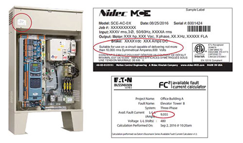
- 620.16(A) Manufacturers must mark their elevator control panels with an equipment short-circuit current rating (SCCR). The SCCR can be based on an assembly product standard listing and labeling, or an approved analysis method, such as UL 508A, Supplement SB.
- 620.16(B) If the elevator control panel SCCR is not equal to or greater than the available fault current, the elevator control panel must not be installed.
- 620.51(D)(2) An elevator control panel must now be field marked with the maximum available fault current along with the date the calculation was made. Further, if there is a change to the available fault current, then this field marking must be revised.
Complying with these new requirements
In order to comply with these requirements a chain of events must occur.
- The electrical system designer calculates the maximum available fault current at the elevator controller.
- The electrical system designer needs to communicate this information to the person responsible for specifying the elevator controller, which is most often the architect.
- The party responsible for procuring the elevator control panel must state the minimum acceptable SCCR or the maximum available fault current where the controller will be installed.
- The elevator controller manufacturer must determine the required elevator controller SCCR as stated in the elevator controller specification and provide an elevator controller SCCR that is equal to or greater than the available fault current that’s indicated in the design documents where there are multiple elevator controllers at different locations.
With these new NEC requirements, there is now the potential that an elevator controller SCCR may be required that’s higher than what elevator manufacturers have historically furnished. As such, elevator controller manufacturers should make the effort to rethink their designs to avoid costly system design changes. For instance, a typical elevator controller may traditionally have SCCR ratings from 5 to 10 kA. However, it is likely that for many elevator controllers, this may not be high enough for the available fault current where they will eventually be installed.
Some elevator controller manufacturers believe this is an issue for the electrical system designer and installer to address and remedy by adding impedance to the system for lowering the available fault current. This, however, can result in a dramatic increase in cost, space availability (lack thereof), and reduced efficiency. For instance, one method to reduce the available fault current is to add an isolation transformer ahead of the elevator controller.
Many new buildings are incorporating an elevator design that does not include an equipment room (sometimes called machine room-less elevators). All equipment in a machine room-less design is installed within the elevator shaft or exterior compartment near the elevator shaft, including the elevator controller and the elevator disconnecting means. In these installations, it is best to design the elevator controller so the elevator controller SCCR is adequate for the available fault current. This is something that can be easily accomplished if the elevator controller manufacturer uses components in combination with overcurrent protective devices that are tested and listed with high combination SCCRs. In many cases, the overcurrent protective devices that are suitable for this level of protection are current-limiting fuses rather than a traditional circuit breaker. In this case, it may be best if the elevator controller manufacturer does not include the elevator disconnecting means (often offered as a circuit breaker) but instead have the installer provide a separate fused disconnect to comply with NEC 620.51(A) and also achieve a high SCCR for the elevator controller when fuses are provided as specified by the elevator controller and marked on the elevator controller nameplate.
Selective Coordination
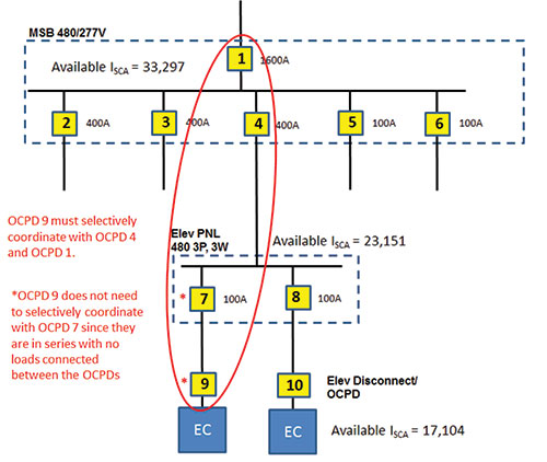
If elevators are supplied by the emergency, legally required standby or critical operation power systems, then selective coordination is required per the 2017 NEC in 700.32, 701.27 or 708.54. Selective coordination is also required for multiple elevators per NEC 620.62. Another important electrical system design consideration for supplying power to multiple elevators is NEC 620.62. NEC 620.62 requires the elevator disconnecting means (fused switch or circuit breaker) to selectively coordinate with all supply-side overcurrent devices. Selective coordination is defined by the NEC as: “Localization of an overcurrent condition to restrict outages to the circuit or equipment affected, accomplished by the selection and installation of overcurrent protective devices and their ratings or settings for the full range of available overcurrents, from overload to the maximum available fault current, and for the full range of overcurrent protective device opening times associated with those overcurrents.”
In order to comply, the electrical system designer must determine the maximum available fault current at the elevator disconnecting means and assure the elevator disconnecting means overcurrent protective device will clear any overcurrent condition, up to the maximum available fault current, before any upstream overcurrent devices will operate. Notice the definition mentions the full range of operating times. This is important as the tradition of using only time-current curves for the analysis of overcurrent device operation is usually not sufficient since the time-current curves traditionally stop at 0.01 second (not time “zero”).
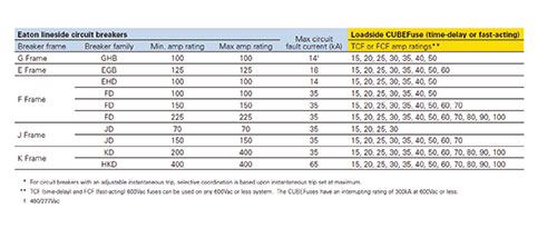
For current-limiting fuses, the information to achieve selective coordination has been available for many years in fuse amp ratio tabular form. These selective coordination tables for current-limiting fuses show the minimum amp ratio required between a pair of fuses of a given type(s) to achieve selective coordination.
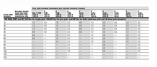
For circuit breakers, time-current curves must be consulted as well as the circuit breaker manufacturer’s selective coordination tables. These circuit breaker selective coordination tables can be used to identify the maximum fault current that a pair of circuit breakers can selectively coordinate. It is important to note, that these selective coordination tables can indicate a lack of selective coordination at a given fault current for circuit breakers that do not show overlap on the time-current curves of the circuit breakers. For some manufacturers, such as Eaton, testing has been completed to determine the selective coordination ability of current-limiting Bussmann TM series fuses with upstream Eaton circuit breakers.
Shunt Tripping
Where the elevator shaft and/or equipment room has a sprinkler fire suppression system installed, the elevator Code requires main line power to the elevator be removed prior to the application of water. This is typically accomplished via a shunt trip device.
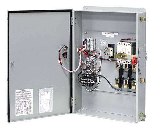
There are options available to achieve this depending upon the customer’s needs. The simplest option is to use a shunt trip circuit breaker in either the feeder supplying the elevator or the elevator disconnect. For elevators with battery lowering systems, an additional contact must be supplied and wired to disable the battery lowering system when the elevator disconnect is manually operated for maintenance. NFPA 72 requires the control circuit between the Fire Alarm System and the shunt trip be monitored for integrity. In addition, the shunt-trip voltage must also be monitored by the Fire Alarm System. Loss of voltage to the control circuit for the disconnecting means shall cause a supervisory signal to be indicated at the control unit and required remote annunciation. In some cases, it may require a means to test the shunt trip operation or have one contact operate the shunt trip of more than one elevator. Per the 2017 NEC , if the elevator is designated as an emergency system load, the disconnect must be protected by a surge protective device (SPD). All of these options and special wiring can be challenging depending upon the location of the shunt trip circuit breaker as well as who has responsibility for providing these additional options. Because of this, several manufacturers offer an all-in-one shunt trip elevator disconnect switch that includes all the prewired accessories needed to comply with the various Code sections.
Typical Elevator Installations
The architect has a choice of either traction or hydraulic elevators. Traction elevators are typically faster and more energy efficient than hydraulic elevators, and are often used for high-rise buildings. Hydraulic elevators are typically more cost effective and used for buildings up to 5-6 stories. Traction elevators are typically installed in a “bank of elevators” where fused switches, or circuit breakers in a panelboard are located in the machine room serving the bank of elevators. Each fused switch or circuit breaker in the panelboard is used as an elevator disconnect. Hydraulic elevator installations are typically supplied from the main switchboard and have an elevator fused switch or circuit breaker in the machine room that serves as the elevator disconnect.
As mentioned, traditional installations of a traction or hydraulic elevator include a separate machine room. The vast majority of equipment serving the elevator is located within this room (i.e., elevator controller). Also located in this room might be, but not limited to: exhaust fan, cooling unit (depending on local requirements and/or requirements set forth by the individual elevator supplier), lighting, voice and/or data drop serving the elevator cab emergency phone, elevator controller primary fused disconnect, elevator feeder shunt-trip circuit (i.e., shunt-trip circuit breaker), elevator cab lighting fused switch, and convenience receptacle(s).
Machine room-less elevator installations incorporate the elevator controller and often the primary disconnecting means in a convenient package that is located within the elevator shaft. However, space is frequently limited within the shaft and as such many ancillary components (shunt trip circuit breakers, fused disconnects) may need to be located outside of the elevator shaft. It is important for design engineers to communicate this with the architect and owner during the design phase, as it will impact space needs elsewhere in the facility to accommodate electrical equipment.
A traditional elevator installation (which includes a machine room) requires access inside the elevator shaft. Convenience receptacles and lighting for maintenance purposes are required at the base of the pit and, in some instances (elevator manufacturer dependent), at the top of the elevator shaft. It is important for the design engineer to coordinate with the architect to determine the elevator manufacturer basis of design to determine if and when additional power and lighting is required.
It is of great importance for the design engineer to communicate with their local authority having jurisdiction (AHJ) to determine fire alarm requirements for the respective elevator installation. While machine room-less designs have been commercially available for many years, their use may still be unknown to some AHJs. Design practices that are acceptable in some jurisdictions may not be in others. As always, the best advice in all instances…do your homework, communicate often, and document decisions made. Years may lapse between the design and installation stages of a project. Good documentation is of key importance to recalling what decisions were made and why.
With the new elevator controller requirements, more attention will be focused on the elevator system. First, it is now clear that elevator controllers must be marked by the manufacturer with their SCCR. The design engineer must identify the available fault current at the elevator controller to the installer so an elevator controller with adequate SCCR can be provided. If this is not done and the available fault current exceeds the elevator controller SCCR, other solutions to reduce fault current must be reviewed or equipment changes and field evaluations may be needed. In addition, requirements for selective coordination and shunt tripping should be complied with as needed for the installation.
What are the Safety Hazards of Inadequate SCC
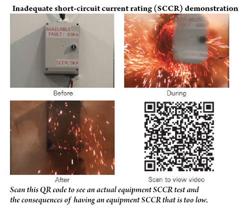
The hazards are external to the equipment enclosure since equipment SCCR testing and evaluation criteria for product standards are most often performed with the enclosure doors closed and latched, and the fault occurring external to the enclosure. Installing electrical equipment where its SCCR is less than the available short-circuit current creates serious safety hazards. These may include:
- Shock: The enclosure becomes energized from conductors pulling out of their terminations or device destruction occurring within the enclosure.
- Fire: The explosive power of the internal devices failing causes the closed and latched door to become ajar and spew flame and molten metal to the exterior. This is a fire hazard to both the facility and personnel.
- Projectile (shrapnel): The enclosure door may blow open or off with fire and failing device debris (shrapnel) shooting out. In laboratory tests, equipment SCCR failures have resulted in enclosure doors explosively blowing off and flying up to 100 feet away. Additionally, the shrapnel, from the rapid failure of internal devices, can be ejected at speeds up to 700 miles per hour.
The author would like to recognize Jonathan Kennedy for his assistance in creating this article.
Air-Conditioning Equipment Installations

Basic three-phase power measurements explained

Safety in Marinas

Find Us on Socials
Raceway connections.
As an installer and an inspector, one common issue I've seeen is incompatible connections associated with raceways connections and fittings.

Safety After the Storm — Operating Portable Generators
Electricity is often one of the initial services to fail during a storm. Many people use portable generators until power is restored.

22 Ways to Make Members Feel Valued
Here are 23 ways that both chapters and the national office can meet today’s major challenge of making members feel valued
Elevator Switches

Mersen’s Type ES Elevator switches are designed for commercial applications where safety, high performance and continuity of service are essential.
Mersen’s Elevator Switches are available in 30-400 amps and 208VAC, 240VAC, 480VAC, 600VAC. They have 5 enclosure types, NEMA Type 1 (indoor), Type 3R (outdoor), Type 4 and 4X (water and dust-tight, corrosion resistant), and Type 12 (drip and dust-tight). They are UL 98 and cUL 508A listed.
Features & Benefits
Best suited for commercial applications.
Fire safety relay for control interface (3 PDT relay with choice of coil voltage).
Oil-tight key switch to test 2 position selector switch.
Oil-tight power enabled indicator light (green, red or white).
Isolated lug neutral (100% or 200%)
Auxiliary and alarm contacts (Form C). Auxiliary contacts change state when switch is in ON position. Alarm contacts change state when switch is in tripped position
Rotary ON/OFF handle.
Accepts padlock in OFF position.
Suitable for Class J fuses.
Related Industries

Publications
- Application and Technical

- Find Authorized Distributors
- About Littelfuse
- Littelfuse Business Center
- Littelfuse University
- Commercial Vehicle Products Portal
- Electronics Technical Resources
- C & K Partner Community
- Search All Automotive Sensor Products Battery Management Battery Mini-Breakers Custom Sensors DC Power Distribution Modules DC Solenoids and Relays Discrete Diodes Discrete IGBTs Discrete Thyristors Fusible Switches and Panels Fuse Blocks Fuseholders and Fuse Accessories Fuses Gas Discharge Tubes Ignition IGBTs LED Protectors Magnetic Sensors and Reed Switches New Products Other Products and Accessories Polymer ESD Suppressors PolyZen Devices Power Semiconductors Protection Relays and Controls PolySwitch Resettable PPTCs Shock Block GFCI SIDACtor Protection Thyristors Silicon Carbide Surge Protection Modules and Devices Switches Temperature Sensors TVS Diode Arrays TVS Diodes Varistors

Automotive Sensors
- Comfort and Convenience
- Passenger Safety
- xEV Sensors
Battery Management
- Battery Combiners
- Battery Isolators
- Electrical Battery Disconnect Switches
- FlexMod Electronic Modules
- Low Voltage Disconnects
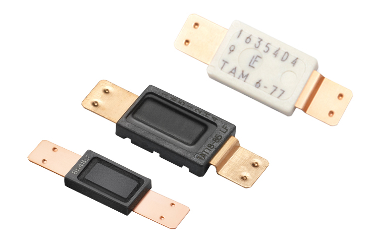
Battery mini-Breakers (Thermal Cutoff Devices)
- Metal Hybrid Protection
Capacitors boosts the current and increases the power factor to an electrical motor.
- Motor Hard Start Capacitors
- Motor Run Capacitors
- Auxiliary Switches for Contactors
- Definite Purpose Contactors
- Current Sensing Resistors
DC Power Distribution Modules
- Auto & Commercial Vehicle Fuse Holders
- Configurable PDM
- Fuse Only PDM
- Hard Wired PDM
- Power Distribution Accessories
- POWR-BLOK Modular Power Distribution
- Unsealed PDM
DC Solenoids and Relays
- Bi-Stable Latching Relays
- CAN Controllers and Plug In Relays
- Mechanical Relays
- Plug In Relays
Solid State Relays
- Specialty Relays
- Standard High Current Relays
- Time Delay and High Power Relays
- High Voltage DC Contactors Relays
DC Vehicle Connectors
- 13-Pole Sockets and Plugs
- 15-Pole Sockets and Plugs
- 15-Pole Spiral Coils
- 2-Pole - 3-Pole Sockets and Plugs
- 7-Pole Sockets and Plugs
- 7-Pole Spiral Coils
- ABS - EBS Sockets and Plugs
- ABS - EBS Spiral Coils
- Connector Accessories
- Greycon Connectors
EMC Components
- Common Mode Noise Filters
- Common Mode Filters with ESD Protection
- Electronic Switches, Connectors, and Harnesses
Fuse Block Fuse Holder and Fuse Accessories
- Bodies, Caps, Covers and Terminals
- Box Cover Units
- Dead Front Fuse Holders
- Electrical Power Distribution Blocks
- Fuse Blocks
- Fuse Modules
- Fuse Pullers
- Fuse Reducers
- Fuse Holder
- Inline Watertight Fuse Holders
- POWR-GARD Fuse Blocks
- Specialty Items
- Telcom Disconnect Switches
- POWR BLOK Modular Power Distribution
- AEC-Q200 Qualified Fuses
- Automotive Aftermarket Products
- Automotive Passenger Car
- Axial Radial Thru Hole Fuses
- Hazardous Area Type Fuses
- Industrial Power and UL Fuses
- Medium Voltage Fuses
- Cartridge Fuses
- Military High Reliability Fuses
- Specialty Power Fuses
- Surface Mount Fuses
Fusible Switches and Panels
- XPress-Ship™ Program
Gas Discharge Tubes
- High Voltage GDT
- Low to Medium Surge GDT
- Medium to High Surge GDT
- Squared GDT
- Very High Surge GDT
- Integrated Circuits
- Magnetic Sensors and Reed Switches
- Custom Sensors
- Hall Effect Sensors
- Magnetic Actuators
- Reed Relays
- Reed Sensors
- Reed Switches

- Transformers
- New Products
Other Products and Accessories
- Accessories
- BusBars and Terminal Blocks
- Circuit Breakers
- Knobs and Nuts
- Pilots, Lamps and Alarms
- Power Distribution
- Speciality Items
- Terminals and Contacts
- Tracto-Trailer and Auto-RV Connectors
- Wiring Accessories
Polymer ESD Suppressors
- PESD Protection Devices
- PULSE-GUARD® ESD Suppressors
- XTREME-GUARD™ ESD Suppressors
Power Semiconductors
- AC Bridge Rectifiers
- Breakover Diodes
- Ignition IGBTs
- IXYS Power Semiconductors and ICs
- Diode Modules
- Discrete IGBTs
- Discrete MOSFETs
- Discrete Thyristors
- Thyristor Modules
- IGBT Modules
- MOSFET Modules
- Thyristor-Diode Modules
- Discrete Diodes
- Fast Diodes and Schottky Products
- Silicon Carbide
- Stacks, Subsystems, and Assemblies
Protection IC
- Load Switch
Protection Relays and Controls
- Alternating Relays
- Arc Flash Detection
- Covers and Mounting Adapters
- Feeder Protection
- Ground Fault Relays
- Flashers and Tower Lighting Controls
- Industrial Products
- Intrinsically Safe Relays
- Motor and Pump Protection
- Pump Controls and Liquid Level Controls
- Relay Current Transformers
- Relay Software
- Resistance Grounding
- Retrofit Kits
- Single Function Relays
- Time Delay Relays
- Trailing Cable Protection
- Voltage Monitoring Relays
PolySwitch Resettable PPTC Fuses
- Battery Strap
- Bladed Devices
- Line Voltage Rated Devices
- Low Resistance
- Radial Leaded
- Surface Mount
- TD and Chip
- Semiconductors
LED Protectors
- PLED 5HT SOT 89
SIDACtor® Protection Thyristors
- Baseband Voice DS1 Protection
- Broadband Optimized Protection
- High Exposure Surge Protection
- Line Circuit Access Switch LCAS Protection
TVS Diode Arrays
- Automotive Qualified
- General Purpose ESD Protection
- Lightning Surge Protection
- Low Capacitance ESD Protection
- Ultra Low Capacitance
Shock-Block® GFCI
- Industrial Shock-Block GFCI
- Shock-Block GFCI Rental Products
Surge Protection Modules and Devices
- LED Lighting Surge Protection Modules
- Type 2 Surge Protection Devices - SPD2 Series
- AC Power Relays
- OptoMOS Power Relays
- OptoMOS Relays
- Ignition Switches
- Manual Battery Disconnect Switches
- Momentary Switches
- Push-Pull Switches
- Rocker Switches
- Rotary Switches and Headlamp Switches
- Plunger Switches
- Special Purpose Switches
- Toggle Switches
- Windshield Wiper Switches

- Temperature Sensors
- Digital Temperature Indicators
- Leaded RTDs
- Leaded Thermistors
- Power Thermistors
- RTD Probes and Assemblies
- Surface Mount Thermistors
- Thermistor Probes and Assemblies
- 2Pro Devices
- Industrial High Energy
- Multi-layer
- Thermally Protected
- Automotive Aftermarket
- Automotive and Commercial Vehicle Aftermarket
- Battery Energy Storage Systems
- Building Automation
- Commercial Vehicle
- Communications Infrastructure
- Consumer Electronics
- Data Center Solutions
- Electrical Contractor
- Electrical Maintenance and Repair
- EV Charging
- Food and Beverage
- LED Lighting
- Military Electronic Parts
- Oil, Gas and Petroleum
- Power Generation
- Renewable Energy
- Water Wastewater
- Custom Circuit Protection Solutions
- DC High-Voltage Solutions
- Electronic Testing Services
- MROplus Industrial Fuse Consolidation
- Application Designs
- Building and Home Automation
- Consumer and Personal Computing
- EV Infrastructure
- General Port Protection
- Li-ion Battery
- Medical Devices
- Power Supply
- Datasheets & Downloads
- Application Guides
- CAD Drawings
- Certification
- Engineering Drawings
- Product Catalogs
- Product Manuals
Datasheets & Downloads
- Application Notes
- Obsoletion Notices
- Peak Let Thru Curves
- Plant Certifications
- Product Literature
- Product Presentations
- Product Specifications
- RoHS Declaration
- Simplified Circuit Diagrams
- SPICE Models
- Supplier Quality
- Technical Articles
- Technical Papers
- Time Current Curve
- Tutorials and Demos
- White Papers
- Online Tools
- Arc-Flash Calculator
- Competitor Cross Reference
- Demos and Tutorials
- ECAD Models
- IBU Relay Selection Guide
- Littelfuse Mobile Apps
- SPD Selection Guide
- Temperature Sensor Selection Guide
- Technical Centers
- Arc-Flash Knowledge Center
- Ceramic, Polymer, and Fuse
- Ground-Fault Knowledge Center
- Relays and Controls

Need the Littelfuse equivalent to a competitor part? Enter the competitor part number here.
Search for the part(s) number you wish to receive samples. Or, visit the sample center page.
Check distributor stock levels by entering in full or partial part numbers
- > Fusible Switches and Panels
LPS Series - Pre-Engineered Shunt Trip POWR-Switch

- LPS Datasheet
- View Part Datasheets
Littelfuse products are not designed for, and shall not be used for, any purpose (including, without limitation, automotive, military, aerospace, medical, life-saving, life-sustaining or nuclear facility applications, devices intended for surgical implant into the body, or any other application in which the failure or lack of desired operation of the product may result in personal injury, death, or property damage) other than those expressly set forth in applicable Littelfuse product documentation. Warranties granted by Littelfuse shall be deemed void for products used for any purpose not expressly set forth in applicable Littelfuse documentation. Littelfuse shall not be liable for any claims or damages arising out of products used in applications not expressly intended by Littelfuse as set forth in applicable Littelfuse documentation. The sale and use of Littelfuse products is subject to Littelfuse Terms and Conditions of Sale, unless otherwise agreed by Littelfuse. "Littelfuse" includes Littelfuse, Inc., and all of its affiliate entities.
Why are Class J fuses used instead of RK1?
For fully-loaded XPress-Ship LPS products click here
Applications
- Elevator circuits
- Data processing rooms
- Building emergency systems
Features/Benefits
- Pre-engineered single unit, which makes procurement easier than systems with multiple components
- Reduces labor costs up to 66% and total installation costs by over 30%
- Pre-installed UL listed Class J fuse holder – unique
- Class J size eliminates the need for any rejection type fuse clips
- Optional features offer flexibility for a variety of applications
- Control power terminal block
- UL Listed package
- Cu and AI wire rated
- Pre-wired control circuits lower installation time
- Lockable operating handle meets all code and safety requirements (Accepts up to 3 locks)
- Every unit is fully tested before delivery
- Control power transformer with fuses and blocks
- Fire safety interface relay
- Key to test switch
- Pilot light ”On”
- Isolated neutral lug
- Mechanical interlock auxiliary contact for hydraulic elevators with automatic recall (5 amp 120 Vac rated)
- Fire alarm voltage monitoring relay
- Option to bypass alarm when performing maintenance (-AZ option)
- XPress-Ship™ service offers 48 Hours direct shipment service on select fully loaded LPS POWR-Switches

- Technical Resources
- Environmental Info
Showing 1 - 3 of 3
- All Document Types 2D Prints 3D Model Application and Design Guides Market Presentations CK Content Cross Reference Customer Presentations Customer Success Stories Design Guides Image New Product Flyers New Product Introductions PEC Documents Product Brochures and Catalogs Rep Training Presentations Sell Sheets Technical Articles and Papers Case Studies Cross Reference Engineering Specifications FAQ Guideform Specifications Infographics New Product Flyers Selection Guides Videos Application Guides Application Notes Articles Brochures CAD Drawings Certification Partner ECAD Models Data Sheets Data Sheets Symbols and Models Engineering Drawings Multimedia Image Titles Instructions Obsoletion Notices Product Change Notifications Peak Let-Thru Curves Plant Certifications Product Brochures Product Catalogs Product Literature Product Manuals Product Presentations Product Specifications RoHS Declaration RT Tables Reports Simplified Circuit Diagrams Software SPICE Models Supplier Quality Technical Articles Technical Papers Test Reports Time Curve Training White Papers xBRL
- Sort By Title A-Z Title Z-A
- Items Per Page 5 10 15 20 50 100 200
Connect with Littelfuse
- Mobile Site
- Capabilities Brochures
- Investor Relations
- Media Coverage
- Privacy Statement
- Sustainability
- Terms & Conditions of Sale
- Website Feedback
- Website Terms of Use
Explore Littelfuse Products
- Check Distributor Stock
- Disclaimers
- Order Samples
Technical Resources & Quality
- Conflict Free Statement
- Supplier Resources
- Supply Chain Transparency
- Technical Documents
Littelfuse, Inc. 8755 West Higgins Road Suite 500, Chicago, IL, 60631 USA, 773-628-1000 Copyright © 2022 Littelfuse, Inc.
We use cookies to collect information about how you interact with our website and to remember you. We use this information to improve and customize your browsing experience and for analytics about our visitors on this website and other media. To find out more about the cookies we use, see our Privacy Policy .
You can change this setting by clicking on OPTIONS. By continuing, you agree to the use of our cookies.
We use cookies to collect information about how you interact with our website and to remember you. We use this information to improve and customize your browsing experience and for analytics about our visitors on this website and other media. By selecting among and accepting to our use of the cookie categories below, you direct Littelfuse to store cookies on your device and disclose information as described in our Privacy Policy .
If you do not direct us to collect any categories of cookies, a single essential cookie will be used in your browser to remember your preference not to be tracked.
Your Privacy
- Performance and Analytical Technologies
Functionality
Targeting or advertising.
When you use our website, we collect personal data about you and your use of the Website, through cookies and analytics tools. We may also collect personal data such as your name, job title, company name, address, email address and telephone number either directly from you or by combining information we collect through other sources.
Because Littelfuse respects your right to privacy, you can choose to modify the cookies option and disallow some of them. Click on the different category headings to learn more and change default settings. However, blocking some types of cookies may impact your experience of the site and the services we are able to offer.
There are cookies which are needed for our website, applications or services to function properly. For example, these cookies remember your preference not to be tracked and identify trusted web traffic.
Performance and analytical technologies
These cookies collect information about how visitors and users use our website, applications, and services. These cookies enable us to improve our website, for instance, by ensuring that users are finding the required information.
These cookies don't collect information that identifies a visitor or user. All information collected by these cookies is aggregated and anonymous.
These cookies allow our website, applications and services to remember choices you make (such as your preferred language) and provide enhanced, more personal features. They may also be used to provide services you have asked for.
The information these cookies collect may be anonymized and they cannot track your browsing activity on other websites.
These cookies are used to deliver advertising that may be relevant to you and your interests. They are also used to limit the number of times you see an advertisement as well as help measure the effectiveness of an advertising campaign.
They remember that you have visited a website and this information is shared with other organizations such as advertisers.

IMAGES
VIDEO
COMMENTS
Elevator Shunt Trip is a function that involves the fire alarm system via heat detectors, shunting the breaker that controls the elevator equipment (typically set to activate 5 degrees before the actual automatic sprinkler head pops.). This in turn powers down the elevator equipment before any automatic sprinkler water is released.
A power shunt trip in an elevator operates simply and reliably. Heat detectors are located in the machine room and at the top of the hoistway, within 24 inches of each sprinkler head.
3006.5 -Shunt Trip. Where elevator hoistways or elevator machine rooms containing elevator control equipment are protected with automatic sprinklers, a means installed in accordance with NFPA 72, Section 3-8.15, Elevator Shutdown, (now 6.15.4) shall be provided to disconnect automatically the main line power supply
In short, if you are written up for testing of initiating and/or shunt-trip devices, you need to call a fire/life safety contractor and/or electrician and possibly your elevator service provider. Still have questions, we're happy to help! Call or email our Chief Problem Solver, Sean (206) 482-5119.
In this video I show the most common way I've seen elevator shunt trip setup and wired. I explain the concept behind elevator shunt trip and then explain how...
3005.5 Shunt trip. Where elevator hoistways, elevator machine rooms, control rooms and control spaces containing elevator control equipment are protected with automatic sprinklers, a means installed in accordance with Section 21.4 of NFPA 72 shall be provided to automatically disconnect the main line power supply to the affected elevator prior ...
ASME A17.1 does not permit water discharge in elevator shafts until electrical power to the elevator cab has been shut down. This situation necessitates some special arrangement, such as a shunt trip or a preaction system, to make sure that water does not flow in the elevator shaft until power shutdown has occurred.
The ASME A17.1 Safety Code for Elevators and Escalators, Rule 102.2(c)(3), requires the shutdown of power to the elevator prior to the application of water in the elevator machine room or hoistway. (Figure 1, Note 2). Shutdown of power is usually accomplished with the use of a shunt trip device in the elevator circuit, and is done for two valid ...
Elevator Shunt Trip - Fire Alarm Requirements. Here are the requirements for heat detector placement, monitoring of power and wiring diagram from 1999 NFPA 72: 3-9.4.1* Where heat detectors are used to shut down elevator power prior to sprinkler operation, the detector shall have both a lower temperature rating and a higher sensitivity as ...
not to shunt trip the breakers feeding the elevator. The shunt trip process is controlled by the Smoke and Heat detectors installed in the elevator shaft itself tied to the shunt trip breakers, not from the auxiliary contacts in the elevator service disconnect. Someone more knowledgeable about such will probably chime in. JAP>
In this video I show the utilization of a Cooper Bussmann Power Module Switch which dramatically simplifies elevator shunt trip. You'll no longer need to two...
The shunt trip is an essential safety feature that allows for remote shut off of the power to the elevator in case of an emergency or malfunction. The wiring diagram provides a visual representation of the electrical connections and components involved in the shunt trip system. It includes various elements such as circuit breakers, relays ...
typically accomplished via a shunt trip device. There are options available to achieve this de-pending upon the customer's needs. The simplest option is to use a shunt trip circuit breaker in either the feeder supplying the elevator or the elevator dis-connect. For elevators with battery lowering systems,
Shunt-Trip Operation The disconnect means is a shunt-trip operated switch. The control power source for the shunt-trip operator is a 120 Vac supply originating in the Siemens Elevator Control switch. Current to the shunt-trip device is switched by an isolation relay, which is in turn controlled by the FACP.
The shutdown of power is accomplished by a shunt trip device in the elevator circuit. This reduces the risk of any potential electrical shock once the water is released into the system. This will also reduce the risk of any elevator car slippage once the cables and hoist system become saturated from the release of water. In addition to turning ...
Features and benefits. The Bussmann series Power Module Switch is a ready-to-install elevator disconnect with popular configurations that can ship in three business days. any single elevator shutdown and disconnect requirement. Easily selectively coordinated, this switch is the best choice for design engineers and electrical contractors that ...
In some cases, it may require a means to test the shunt trip operation or have one contact operate the shunt trip of more than one elevator. Per the 2017 NEC, if the elevator is designated as an emergency system load, the disconnect must be protected by a surge protective device (SPD). All of these options and special wiring can be challenging ...
3005.5 Shunt trip. Where elevator hoistways, elevator machine rooms, control rooms and control spaces containing elevator control equipment are protected with automatic sprinklers, a means installed in accordance with Section 21.4 of NFPA 72 shall be provided to automatically disconnect the main line power supply to the affected elevator prior ...
This video highlights how to wire elevator shunt trip using an addressable system sensor type relay, while also supervising for power loss with an MR-101 and...
Mersen's Type ES Elevator switches (Fusible shunt trip switch) are designed for commercial applications where safety, high performance and continuity of service are essential. Most commonly used for elevator shafts and machine rooms to remotely disconnect main power prior to the activation of a sprinkler system. ... Mersen's Elevator ...
The Littelfuse® LPS Series provides a simple and economical solution for applications that require selective coordination and shunt trip capabilities. Utilizes Class J time-delay fuses that are easily coordinated with other system overcurrent devices. The shunt trip capability allows the LPS Series to meet the ANSI/ASME standard that requires ...