
- Chrysler Manuals
- Voyager 2023
- Owner's manual

Chrysler Voyager 2023 Owner's Manual
- page of 256 Go / 256
Table of Contents
- Introduction
- Symbols Key
- Vehicle Modifications/Alterations
- Symbol Glossary
- Getting to Know Your Vehicle
- Ignition Switch
- Keyless Enter 'N Go™ Ignition
- Remote Start - if Equipped
- How to Use Remote Start
- To Exit Remote Start Mode
- Remote Start Front Defrost Activation
- If Equipped
- Remote Start Comfort Systems - if Equipped
- Remote Start Windshield Wiper De-Icer Activation - if Equipped
- Remote Start Cancel Message
- Vehicle Security System - if Equipped
- To Arm the System
- To Disarm the System
- Rearming of the System
- Security System Manual Override
- Manual Door Locks
- Power Door Locks - if Equipped
- Keyless Enter N G O Passive Entry
- Automatic Unlock Doors on Exit - if Equipped
- Manual Sliding Side Door
- Power Sliding Side Door - if Equipped
- Child Protection Door Lock System - Rear Doors
- Steering Wheel
- Tilt/Telescoping Steering Column
- Heated Steering Wheel - if Equipped
- (Front Seats) - if Equipped
- Manual Adjustment
- Manual Adjustment (Rear Seats)
- Power Adjustment (Front Seats) - if Equipped
- Heated Seats
- Head Restraints
- Uconnect Voice Recognition
- Introducing Voice Recognition
- Basic Voice Commands
- Get Started
- Additional Information
- Inside Rearview Mirror
- Illuminated Vanity Mirrors - if Equipped
- Outside Mirrors
- Conversation Mirror
- Power Mirrors - if Equipped
- Outside Mirrors Folding Feature
- Heated Mirrors - if Equipped
- Exterior Lights
- Multifunction Lever
- Headlight Switch
- Daytime Running Lights (Drls) - if Equipped
- High/Low Beam Switch
- Flash-To-Pass
- Automatic Headlights - if Equipped
- Headlight Time Delay - if Equipped
- Lights-On Reminder
- Turn Signals
- Lane Change Assist - if Equipped
- Battery Protection
- Interior Lights
- Interior Courtesy Lights
- Windshield Wiper and Washers
- Windshield Wiper Operation
- Rain Sensing Wipers - if Equipped
- Rear Wiper and Washer
- Climate Controls
- Manual Climate Control Descriptions and
- Climate Voice Commands
- Operating Tips
- Interior Storage and Equipment
- USB/AUX Control
- Power Outlets
- Power Windows
- Automatic Window Features
- Reset Auto up
- Wind Buffeting
- To Unlock/Open the Liftgate
- To Lock/Close the Liftgate
- Power Liftgate - if Equipped
- Cargo Area Features
- Getting to Know Your Instrument Panel
- Base Instrument Cluster
- Base Instrument Cluster Descriptions
- Premium Instrument Cluster
- Premium Instrument Cluster Descriptions
- Instrument Cluster Display
- Instrument Cluster Display Location and Controls
- Oil Life Reset
- Keysense Cluster Messages
- Instrument Cluster Display Menu Items
- Battery Saver On/Battery Saver Mode Message - Electrical Load Reduction Actions - if Equipped
- Warning Lights and Messages
- Red Warning Lights
- Yellow Warning Lights
- Yellow Indicator Lights
- Green Indicator Lights
- White Indicator Lights
- Blue Indicator Lights
- Onboard Diagnostic System - Obd II
- Onboard Diagnostic System (OBD II) Cybersecurity
- Emissions Inspection and Maintenance
- Starting and Operating
- Starting the Engine
- Normal Starting
- Cold Weather Operation
- (Below -22°F or −30°C)
- After Starting - Warming up the Engine
- If Engine Fails to Start
- To Turn off the Engine Using ENGINE START/STOP Button
- Engine Block Heater - if Equipped
- Engine Break-In Recommendations
- Parking Brake
- Electric Park Brake (EPB)
- Automatic Transmission
- Ignition Park Interlock
- Brake/Transmission Shift Interlock (BTSI) System
- 9-Speed Automatic Transmission
- Gear Ranges
- Active Noise Cancellation
- Power Steering
- Stop/Start System - if Equipped
- Autostop Mode
- Possible Reasons the Engine Does Not Autostop
- To Start the Engine While in Auto Stop/Start
- To Manually Turn off the Stop/Start System
- To Manually Turn on the Stop/Start System
- System Malfunction
- Cruise Control Systems - if Equipped
- Cruise Control
- Parksense Rear Park Assist
- Parksense Sensors
- Parksense Warning Display
- Parksense Display
- Enabling and Disabling Parksense
- Service the Parksense Rear Park Assist System
- Cleaning the Parksense System
- Parksense System Usage Precautions
- Parkview Rear Back up Camera
- Refueling the Vehicle
- Vehicle Loading
- Certification Label
- Trailer Towing
- Common Towing Definitions
- Trailer Hitch Classification
- Trailer Towing Weights
- Vehicle Loading Chart
- Trailer and Tongue Weight
- Towing Requirements
- Towing Tips
- Recreational Towing (Behind Motorhome)
- Towing this Vehicle Behind Another Vehicle
- Driving Tips
- Driving on Slippery Surfaces
- Driving through Water
- Uconnect Systems
- Cybersecurity
- Uconnect Settings
- Customer Programmable Features
- Radio Operation and Mobile Phones
- Regulatory and Safety Information
- Safety Features
- Anti-Lock Brake System (ABS)
- Rear Seat Reminder Alert (RSRA)
- Electronic Brake Control (EBC) System
- Auxiliary Driving Systems
- Blind Spot Monitoring (BSM) - if Equipped
- Forward Collision Warning (FCW) with Mitigation - if Equipped
- System (TPMS)
- Occupant Restraint Systems
- Occupant Restraint Systems Features
- Important Safety Precautions
- Seat Belt Systems
- Supplemental Restraint Systems (SRS)
- Child Restraints
- Safety Tips
- Transporting Passengers
- Transporting Pets
- Connected Vehicles
- The Vehicle
- Periodic Safety Checks You Should Make Outside the Vehicle
- Exhaust Gas
- Carbon Monoxide Warnings
- In Case of Emergency
- Hazard Warning Flashers
- Sos and Assist Mirror - if Equipped
- Jacking and Tire Changing - if Equipped
- Preparations for Jacking
- Jack and Spare Tire Location
- Equipment Removal
- Jacking Instructions
- Road Tire Installation
- Portable Air Compressor - if Equipped
- Return Inflatable Spare Tire
- Tire Service Kit - if Equipped
- Jump Starting
- Preparations for Jump Start
- Jump Starting Procedure
- Refueling in Emergency - if Equipped
- If Your Engine Overheats
- Manual Park Release
- Freeing a Stuck Vehicle
- Towing a Disabled Vehicle
- Enhanced Accident Response System (Ears)
- Event Data Recorder (Edr)
- Servicing and Maintenance
- Scheduled Servicing
- Maintenance Plan
- Engine Compartment
- Checking Oil Level
- Adding Washer Fluid
- Maintenance-Free Battery
- Pressure Washing
- Vehicle Maintenance
- Engine Oil Filter
- Engine Air Cleaner Filter
- Accessory Drive Belt Inspection
- Air Conditioner Maintenance
- Body Lubrication
- Windshield Wiper Blades
- Exhaust System
- Cooling System
- Brake System
- Bulb Replacement
- Tire Safety Information
- Tires - General Information
- Spare Tires - if Equipped
- Wheel and Wheel Trim Care
- Snow Traction Devices
- Tire Rotation Recommendations
- Department of Transportation Uniform Tire Quality Grades
- Traction Grades
- Temperature Grades
- Storing the Vehicle
- Protection from Atmospheric Agents
- Body and Underbody Maintenance
- Preserving the Bodywork
- Seats and Fabric Parts
- Plastic and Coated Parts
- Leather Surfaces
- Glass Surfaces
- Technical Specifications
- Vehicle Identification Number (Vin)
- Wheel and Tire Torque Specifications
- Torque Specifications
- Fuel Requirements
- Reformulated Gasoline
- Gasoline/Oxygenate Blends
- Do Not Use E-85 in Non-Flex Fuel Vehicles
- CNG and LP Fuel System Modifications
- Methylcyclopentadienyl Manganese Tricarbonyl (MMT) in Gasoline
- Materials Added to Fuel
- Fuel System Cautions
- Fluid Capacities
- Engine Fluids and Lubricants
- Chassis Fluids and Lubricants
- Customer Assistance
- Suggestions for Obtaining Service for Your Vehicle
- Prepare for the Appointment
- Preparea List
- Be Reasonable with Requests
- If You Need Assistance
- Roadside Assistance
- FCA US LLC Customer Center
- FCA Canada Inc. Customer Center
- Puerto Rico and US Virgin Islands
Advertisement
Quick Links
- 1 Getting to Know Your Vehicle
- 2 Getting to Know Your Instrument Panel
- Download this manual
Related Manuals for Chrysler Voyager 2023

Summary of Contents for Chrysler Voyager 2023
- Page 1 2023 VOYAGER O W N E R ’ S M A N U A L...
- Page 2 ROADSIDE ASSISTANCE HOURS, DAYS A WEEK AT YOUR SERVICE. 1-800-521-2779 CALL OR VISIT CHRYSLER.RSAHELP.COM (USA) 1-800-363-4869 CALL OR VISIT FCA.ROADSIDEAID.COM (CANADA) SERVICES: Flat Tire Service, Out Of Gas/Fuel Delivery, Battery Jump Assistance, Lockout Service and Towing Service Please see the Customer Assistance chapter in this Owner’s Manual for further information.
Page 3: Table Of Contents
- Page 4 INTRODUCTION STEERING WHEEL .............. 22 Lights-On Reminder............. 41 Tilt/Telescoping Steering Column ......22 Turn Signals ..............41 SYMBOLS KEY ............... 7 Heated Steering Wheel — If Equipped......22 Lane Change Assist — If Equipped ......41 VEHICLE MODIFICATIONS/ALTERATIONS ......7 Battery Protection ............41 SEATS ...................
- Page 5 GETTING TO KNOW YOUR STARTING AND OPERATING PARKSENSE REAR PARK ASSIST — IF EQUIPPED ..............87 INSTRUMENT PANEL STARTING THE ENGINE............75 ParkSense Sensors ............. 88 Normal Starting ............75 BASE INSTRUMENT CLUSTER ...........59 ParkSense Warning Display........88 AutoPark...............75 Base Instrument Cluster Descriptions....... 60 ParkSense Display ............
- Page 6 MULTIMEDIA SAFETY TIPS ..............167 REFUELING IN EMERGENCY – IF EQUIPPED ....187 Transporting Passengers ......... 167 IF YOUR ENGINE OVERHEATS.........187 UCONNECT SYSTEMS ............. 104 Transporting Pets ............ 167 MANUAL PARK RELEASE ..........188 CYBERSECURITY ............. 104 Connected Vehicles ..........167 FREEING A STUCK VEHICLE ...........189 UCONNECT SETTINGS............
- Page 7 CUSTOMER ASSISTANCE Exhaust System ............203 INTERIORS ............... 233 Cooling System............204 Seats And Fabric Parts..........233 SUGGESTIONS FOR OBTAINING SERVICE FOR YOUR Brake System ............206 Plastic And Coated Parts.......... 234 VEHICLE ................240 Automatic Transmission .......... 207 Leather Surfaces ............234 Prepare For The Appointment ........240 Fuses .................
Page 8: Introduction
Page 9: symbols key.
- Page 10 Yellow Warning Lights Red Warning Lights Anti-Lock Brake System (ABS) Warning Light Engine Coolant Temperature Warning Light page 70 page 69 Ú Ú Electric Park Brake Warning Light Hood Open Warning Light page 70 Ú page 69 Ú Electronic Stability Control (ESC) Active Warning Light Liftgate Open Warning Light page 70 page 69...
- Page 11 Yellow Warning Lights Green Indicator Lights Service Stop/Start System Warning Light Parking/Headlights On Indicator Light page 71 page 72 Ú Ú Tire Pressure Monitoring System (TPMS) Warning Light Stop/Start Active Indicator Light page 71 page 72 Ú Ú Turn Signal Indicator Lights Yellow Indicator Lights page 72 Ú...
Page 12: Getting To Know Your Vehicle
- Page 13 GETTING TO KNOW YOUR VEHICLE Key Left Vehicle Feature Perchlorate Material — special handling may apply. Remove the battery by sliding the battery rearward in See www.dtsc.ca.gov/hazardouswaste/perchlorate for its pocket until the battery lifts up. Remove the If a valid key fob is no longer detected inside the vehicle further information.
Page 14: Sentry Key
- Page 15 GETTING TO KNOW YOUR VEHICLE START WARNING! The engine will start (when foot is on the brake pedal) Allowing children to be in a vehicle unattended is The engine only runs in the ON/RUN ignition position or dangerous for a number of reasons. A child or others from a Remote Start request.
Page 16: Remote Start - If Equipped
Page 17: remote start front defrost activation, page 18: vehicle security system - if equipped, page 19: power door locks - if equipped, page 20: keyless enter n g o passive entry, page 21: automatic unlock doors on exit - if equipped, page 22: manual sliding side door, page 23: child protection door lock system - rear doors, page 24: steering wheel, page 25: seats, page 26: manual adjustment.
- Page 27 GETTING TO KNOW YOUR VEHICLE WARNING! WARNING! Do not ride with the seatback reclined so that the If not properly latched, the seat could become loose. shoulder belt is no longer resting against your chest. Personal injuries could result. In a collision you could slide under the seat belt, which could result in serious injury or death.
- Page 28 GETTING TO KNOW YOUR VEHICLE NOTE: Slide the lever upwards, or if equipped, pull the handle forward, to unlock the seatback. The seatback may lock into the fold-flat position. Use the recline lever to unlock the seatback. If equipped with Stow ‘n Go seating: when returning the seat to the original position, the headrest must be folded back to the original position.
- Page 29 GETTING TO KNOW YOUR VEHICLE Easy Entry — With The Seat Folded Flat Exit For Third Row Passengers — Stow ‘n Go Seats Only The seats can be folded and tilted for more accessibility If the second row is equipped with Stow ‘n Go, third row for passengers to enter and exit the third row.
- Page 30 GETTING TO KNOW YOUR VEHICLE To remove the seat, pull the release strap to release Reinstalling Seat Tilt seat rearward to lock the seat back into its original the rear latches. position. To reinstall the seat: With the seat tilted forward, Tilt the back of the seat to the upward position.
- Page 31 GETTING TO KNOW YOUR VEHICLE Lower the center head restraint down to the Pulling strap “2” releases the seatback to return to its seatback by pushing the button on the guide and full upright position. pushing the head restraint down. Pull release strap marked “1”...
- Page 32 GETTING TO KNOW YOUR VEHICLE Stow 'n Go Seating For information on storage bin function with the Remove the plastic storage bin from the storage area, and store in a safe location. seats rearward page 50. Ú On vehicles equipped with Stow 'n Go seating, the second Fold the armrest upward and stow the seat by Pull the latch located near the second row seat to and third row seats can be folded into the floor for...
- Page 33 GETTING TO KNOW YOUR VEHICLE TO UNSTOW SECOND ROW SEATS Close the floor by pulling the floor panel backwards by Readjust the front seat as needed, and replace the the bottom corner edge of the panel. floor mat (if equipped). To unstow the seat from the floor, move the front seat all the way forward using the manual seat adjustment bar.
- Page 34 GETTING TO KNOW YOUR VEHICLE Pull the latch located near the second row seat to Pull the strap located on the seat and pull the seat open the floor panel. out of the storage area. Push the seat rearward making sure that it locks into the floor. Fold the seatback into the upright position and pull the headrest up.
Page 35: Power Adjustment (Front Seats) - If Equipped
Page 36: heated seats, page 37: head restraints.
- Page 38 GETTING TO KNOW YOUR VEHICLE remove the head restraint. To reinstall the head restraint, NOTE: WARNING! put the head restraint posts into the holes and push To remove the center head restraint, raise it as far as it downward. Then, adjust the head restraint to the can go.
Page 39: Uconnect Voice Recognition
Page 40: mirrors, page 41: power mirrors - if equipped, page 42: daytime running lights (drls) - if equipped, page 43: headlight time delay - if equipped, page 44: windshield wiper and washers, page 45: rain sensing wipers - if equipped, page 46: rear wiper and washer.
- Page 47 GETTING TO KNOW YOUR VEHICLE Recirculation Button Front Temperature Control mode with maximum temperature settings for best windshield and side window defrosting and defogging. Press and release this button to change the system These buttons provide the driver and passenger with Performing this function will cause the Automatic between recirculation mode and outside air mode.
- Page 48 GETTING TO KNOW YOUR VEHICLE Blower Control Controlling The Rear Climate Controls direction. There is a shut-off wheel located below the air vanes to shut off or adjust the amount of airflow from From The Front MTC Display/Touchscreen Blower Control is used to regulate the amount these outlets.
- Page 49 GETTING TO KNOW YOUR VEHICLE REAR TEMPERATURE CONTROL PANEL MODE Rear Manual Temperature Control (MTC) These buttons provide the rear passengers with Press this button on the touchscreen to change The rear Manual Temperature Control (MTC) system has independent temperature control. the air distribution mode to Panel Mode.
Page 50: Climate Voice Commands
Page 51: interior storage and equipment.
- Page 52 GETTING TO KNOW YOUR VEHICLE CAUTION! The storage drawer must be closed while driving. If left open during a collision, additional damage may occur to property or the drawer mechanism. Front Seatback Storage — If Equipped The front seatbacks have a storage pocket on some models.
- Page 53 GETTING TO KNOW YOUR VEHICLE NOTE: CAUTION! CAUTION! Push the lock rod inward for the locked position. The storage bin cover must lie flat and be latched to The storage bin cover must lie flat and be latched to ...
Page 54: Usb/Aux Control
- Page 55 GETTING TO KNOW YOUR VEHICLE NOTE: In addition to the front power outlet, there may also be a power outlet located in the rear cargo area. All accessories connected to the battery powered outlets should be removed or turned off when the vehicle is not in The rear power outlet is located in the right rear cargo use to protect the battery against discharge.
Page 56: Windows
Page 57: automatic window features, page 58: hood, page 59: to lock/close the liftgate, page 60: cargo area features, page 61: getting to know your instrument panel, page 62: base instrument cluster descriptions, page 63: premium instrument cluster, page 64: premium instrument cluster descriptions, page 65: oil life reset, page 66: keysense cluster messages.
- Page 67 GETTING TO KNOW YOUR INSTRUMENT PANEL Fuel Economy Stop / Start – If Equipped Oil Pressure Displays the actual oil pressure. Push and release the up or down arrow button Push and release the up or down arrow button until the Fuel Economy Menu item is highlighted in the until the Stop/Start menu title is displayed in the Oil Life instrument cluster display.
Page 68: Battery Saver On/Battery Saver Mode Message - Electrical Load Reduction Actions - If Equipped
Page 69: warning lights and messages.
- Page 70 GETTING TO KNOW YOUR INSTRUMENT PANEL Battery Charge Warning Light Door Open Warning Light — If Equipped NOTE: The light may flash momentarily during sharp cornering This warning light will illuminate when the This warning light will illuminate when a door is maneuvers, which change fluid level conditions.
- Page 71 GETTING TO KNOW YOUR INSTRUMENT PANEL Liftgate Open Warning Light NOTE: on. When driving, if the driver or front passenger seat belt remains unbuckled, the Seat Belt Reminder Light will flash This light may turn on if the accelerator and brake pedals This warning light will illuminate when the or remain on continuously and a chime will sound are pressed at the same time.
Page 72: Yellow Warning Lights
- Page 73 GETTING TO KNOW YOUR INSTRUMENT PANEL Service Stop/Start System Warning Light — vehicle has tires of a different size than the size indicated CAUTION! on the vehicle placard or tire inflation pressure label, you If Equipped should determine the proper tire inflation pressure for Prolonged driving with the Malfunction Indicator This warning light will illuminate when the those tires.
Page 74: Yellow Indicator Lights
Page 75: blue indicator lights, page 76: emissions inspection and maintenance, page 77: starting and operating.
- Page 78 STARTING AND OPERATING ALWAYS DO A VISUAL CHECK that your vehicle is in PARK AutoPark will engage when all of these conditions are met: WARNING! by looking for the “P” in the instrument cluster display and Vehicle is equipped with a gear selector on the gear selector.
Page 79: Cold Weather Operation
Page 80: to turn off the engine using engine start/stop button, page 81: parking brake.
- Page 82 STARTING AND OPERATING Brake Service Mode To disengage the parking brake while the vehicle is in WARNING! motion, release the switch. If the vehicle is brought to a We recommend having your brakes serviced by an complete stop using the parking brake, when the vehicle ...
Page 83: Automatic Transmission
Page 84: brake/transmission shift interlock (btsi) system.
- Page 85 STARTING AND OPERATING If the transmission becomes extremely hot, the CAUTION! WARNING! Transmission Temperature Warning Light will illuminate, a warning message will appear in the instrument cluster, Before moving the transmission gear selector out of Do not coast in NEUTRAL and never turn off the ignition to and the transmission may operate differently until the PARK, you must start the engine, and also press the coast down a hill.
Page 86: Active Noise Cancellation
Page 87: stop/start system - if equipped, page 88: to manually turn off the stop/start system, page 89: parksense rear park assist, page 90: parksense sensors.
- Page 91 STARTING AND OPERATING Rear ParkSense Arcs 1 — Continuous Tone/Flashing Arc 4 — Slow Tone/Solid Arc 2 — Fast Tone/Flashing Arc 5 — Slow Tone/Solid Arc 3 — Fast Tone/Flashing Arc 6 — Single 1/2 Second Tone/Solid Arc...
- Page 92 STARTING AND OPERATING The vehicle is close to the obstacle when the warning display shows one flashing arc and sounds a continuous tone. The following chart shows the warning alert operation when the system is detecting an obstacle: WARNING ALERTS Rear Distance Greater than 79-59 inches...
Page 93: Enabling And Disabling Parksense
Page 94: parkview rear back up camera, page 95: refueling the vehicle, page 96: trailer towing.
- Page 97 STARTING AND OPERATING Gross Combination Weight Rating (GCWR) Trailer Sway Control (TSC) Weight-Distributing Hitch The GCWR is the total permissible weight of your vehicle The TSC can be a mechanical telescoping link that can be A Weight-Distributing Hitch works by applying leverage through and trailer when weighed in combination.
Page 98: Trailer Hitch Classification
Page 99: trailer towing weights.
- Page 100 STARTING AND OPERATING Max Cargo With Maximum Number Of Persons / Weight Of Occupants Max Cargo No Trailer Maximum Trailer TW TW 360 lb (163 kg) 1,205 lb (546 kg) – 360 lb (163 kg) = 845 lb (383 kg) 2 People / 300 lb (136 kg) 1,205 lb (546 kg) 845 lb (383 kg)
Page 101: Trailer And Tongue Weight
- Page 102 STARTING AND OPERATING Towing Requirements — Tires The electrical connections are all complete to the vehicle WARNING! but you must mate the harness to a trailer connector. Do not attempt to tow a trailer while using a compact Refer to the following illustrations. ...
Page 103: Towing Tips
Page 104: driving tips, page 105: driving through water, page 106: multimedia, page 107: uconnect settings.
- Page 108 MULTIMEDIA KeySense The vehicle’s KeySense settings are protected by a unique four-digit PIN, which the vehicle owner creates when accessing the specific settings for the first time. This four-digit PIN can only be reset by an authorized dealer. After pressing the KeySense button on the touchscreen, and entering the KeySense PIN, the following settings will be available: NOTE: Depending on the vehicle’s options, feature settings may vary.
- Page 109 MULTIMEDIA My Profile When the My Profile button is pressed on the touchscreen, the system displays options related to the vehicle’s profiles. NOTE: Depending on the vehicle’s options, feature settings may vary. Setting Name Description This setting will change the language of the Uconnect system and Instrument Cluster Display. The available languages Language are English, Français, Español, and Italiano.
- Page 110 MULTIMEDIA Setting Name Description Voice Options This setting will allow you to change the voice options for the radio to “Male” or “Female”. Wake Up Word This setting will allow you to turn the voice recognition “Wake Up” word on or off. Voice Barge-in This setting will allow you to turn the voice recognition barge-in feature on or off.
- Page 111 MULTIMEDIA Display After pressing the Display button on the touchscreen, the following settings will be available: NOTE: Depending on the vehicle’s options, feature settings may vary. Setting Name Description This setting will change the language of the Uconnect system and Instrument Cluster Display. The available languages Language are English, Français, Español, and Italiano.
- Page 112 MULTIMEDIA Safety & Driving Assistance After pressing the Safety & Driving Assistance button on the touchscreen, the following settings will be available: NOTE: Depending on the vehicle’s options, feature settings may vary. Setting Name Description This setting will change the distance at which the Forward Collision Warning (FCW) alert sounds. The “Medium” Forward Collision Warning Sensitivity —...
- Page 113 MULTIMEDIA Clock & Date After pressing the Clock & Date button on the touchscreen, the following settings will be available: NOTE: Depending on the vehicle’s options, feature settings may vary. Setting Name Description Sync Time With GPS This setting will sync the time to the GPS receiver in the system. The system will control the time via the GPS location. Set Time This setting will allow you to manually set the time of your clock.
- Page 114 MULTIMEDIA Setting Name Description Do Not Disturb All This setting will open the “Do Not Disturb All” settings menu. The available options are “On” and “Off”. Enable Two Active Phones This setting will enable or disable two active phones with the vehicle. The setting options are “On” and “Off”. Phone Pop-Ups Displayed In Cluster This setting will activate phone message pop-ups in the Instrument Cluster Display.
- Page 115 MULTIMEDIA Camera When the Camera button is pressed on the touchscreen, the system displays the options related to the vehicle’s camera features. NOTE: Depending on the vehicle’s options, feature settings may vary. Setting Name Description ParkView Backup Camera Delay This setting will add a timed delay to the ParkView Backup Camera when shifting out of REVERSE. ParkView Backup Camera Active Guidelines This setting will turn the ParkView Backup Camera Active Guidelines on or off.
- Page 116 MULTIMEDIA Lights When the Lights button is pressed on the touchscreen, the system displays the options related to the vehicle’s exterior and interior lights. NOTE: When the “Daytime Running Lights” feature is selected, the daytime running lights can be turned on or off. This feature is only allowed by law in the country of the vehicle purchase. ...
- Page 117 MULTIMEDIA Doors & Locks After pressing the Doors & Locks button on the touchscreen, the following settings will be available: Setting Name Description Auto Unlock On Exit This setting will unlock the doors when any of the doors are opened from the inside. Flash Lights With Lock This setting will allow you to turn the flashing of the lights when the Lock button is pushed on the key fob on or off.
- Page 118 MULTIMEDIA Seats & Comfort When the Seats & Comfort button is pressed on the touchscreen, the system displays the options related to the vehicle’s comfort systems when remote start has been activated or the vehicle has been started. NOTE: Depending on the vehicle’s options, feature settings may vary. Setting Name Description This setting will activate the vehicle’s comfort systems and heated seats or heated steering wheel when the vehicle is...
- Page 119 MULTIMEDIA Audio When the Audio button is pressed on the touchscreen, the system displays options related to the vehicle’s sound system. These settings can change the audio location within the vehicle, adjust the bass or treble levels, and auto-play settings from an audio device or smartphone. NOTE: Depending on the vehicle’s options, feature settings may vary.
- Page 120 MULTIMEDIA Notifications When the Notifications button is pressed on the touchscreen, the system displays the options related to Notifications for the system. NOTE: Depending on the vehicle’s options, feature settings may vary. Setting Name Description App Drawer Favoriting Popups This setting turns the App Favorited pop-up on or off. App Drawer Unfavoriting Popups This setting turns the App Unfavorited pop-up on or off.
- Page 121 MULTIMEDIA Software Updates When the Software Updates button is pressed on the touchscreen, the system will display information on updating the Uconnect system’s software. NOTE: Depending on the vehicle’s options, feature settings may vary. Setting Name Description Software Downloads over Wi-Fi This setting will allow software updates to happen over Wi-Fi.
Page 122: Radio Operation And Mobile Phones
Page 123: safety, page 124: electronic brake control (ebc) system.
- Page 125 SAFETY Electronic Brake Force Distribution (EBD) Electronic Stability Control (ESC) WARNING! The EBD function manages the distribution of the braking ESC enhances directional control and stability of the Electronic Stability Control (ESC) cannot prevent the torque between the front and rear axles by limiting braking vehicle under various driving conditions.
- Page 126 SAFETY ESC Operating Modes Activation/Malfunction Indicator Light begins to flash WARNING! during acceleration, ease up on the accelerator and apply Depending upon model and mode of operation, the ESC as little throttle as possible. Be sure to adapt your speed ...
- Page 127 SAFETY Towing With HSA Rain Brake Support (RBS) The following conditions must be met in order for HSA to activate: HSA will also provide assistance to mitigate roll back while RBS may improve braking performance in wet conditions. The feature must be enabled. towing a trailer.
Page 128: Auxiliary Driving Systems
- Page 129 SAFETY The BSM system notifies the driver of objects in the Overtaking Traffic detection zones by illuminating the BSM Warning Light If you pass another vehicle slowly with a relative speed located in the outside mirrors in addition to sounding an less than 15 mph (24 km/h) and the vehicle remains in audible (chime) alert and reducing the radio volume the blind spot for approximately 1.5 seconds, the warning...
- Page 130 SAFETY Rear Cross Path (RCP) The BSM system is designed not to issue an alert on stationary not be able to alert the driver. Additionally, if your vehicle objects such as guardrails, posts, walls, foliage, berms, snow is obscured by a flat object on one side the system can RCP is intended to aid the driver when backing out of parking banks, car washes, etc.
Page 131: Forward Collision Warning (Fcw) With Mitigation - If Equipped
- Page 132 SAFETY FCW Braking Status And Sensitivity NOTE: WARNING! Changing the FCW status to “Only Warning” prevents The FCW Sensitivity and Active Braking status are Forward Collision Warning (FCW) is not intended the system from providing limited active braking, or programmable through the Uconnect system to avoid a collision on its own, nor can FCW detect additional brake support if the driver is not braking...
Page 133: System (Tpms)
- Page 134 SAFETY The TPMS will warn the driver of a low tire pressure if the NOTE: NOTE: tire pressure falls below the low-pressure warning limit for When filling warm tires, the tire pressure may need to be The TPMS is not intended to replace normal tire care any reason, including low temperature effects and natural increased up to an additional 4 psi (28 kPa) above the and maintenance, or to provide warning of a tire failure...
- Page 135 SAFETY TIRE PRESSURE MONITORING SYSTEM LOW The TPMS consists of the following components: Vehicles With Compact Spare — If Equipped PRESSURE WARNINGS Receiver module The compact spare tire does not have a Tire Pressure Monitoring System sensor. Therefore, the TPMS will not ...
Page 136: Occupant Restraint Systems
Page 137: seat belt systems.
- Page 138 SAFETY WARNING! WARNING! WARNING! A lap belt worn too high can increase the risk of injury Do not allow people to ride in any area of your vehicle A seat belt that is worn under your arm is dangerous. in a collision.
- Page 139 SAFETY Lap/Shoulder Belt Operating Instructions Position the shoulder belt across the shoulder and chest with minimal, if any slack so that it is comfortable and not Enter the vehicle and close the door. Sit back and resting on your neck. The retractor will withdraw any slack adjust the seat.
- Page 140 SAFETY Adjustable Upper Shoulder Belt Anchorage Remove the mini-latch plate and regular latch plate WARNING! from its stowed position in the headliner slightly In the front and second row outboard seats the shoulder behind the second or third row seat. ...
- Page 141 SAFETY Route the shoulder belt to the inside of the left head Sit back in seat. Slide the regular latch plate up the restraint. webbing as far as necessary to allow the seat belt to go around your lap. Latch Plate And Buckle Connected Position the lap belt so that it is snug and lies low across your hips, below your abdomen.
- Page 142 SAFETY Seat Belt Extender Seat Belts And Pregnant Women 10. To disengage the mini-latch plate from the mini-buckle for storage, insert the regular latch plate If a seat belt is not long enough to fit properly, even when into the center red slot on the mini-buckle. The seat the webbing is fully extended and the adjustable upper belt will automatically retract to its stowed position.
- Page 143 SAFETY Seat Belt Pretensioner Switchable Automatic Locking Retractors (ALR) The front outboard seat belt system is equipped with pretensioning devices that are designed to remove slack The seat belts in the passenger seating positions are from the seat belt in the event of a collision. These devices equipped with a Switchable Automatic Locking Retractor may improve the performance of the seat belt by removing (ALR) which is used to secure a child restraint system...
- Page 144 SAFETY Seat Belt Park Stitch — If Equipped If the passenger seating position is equipped with an ALR How To Engage The Automatic Locking Mode and is being used for normal usage, only pull the seat belt Buckle the combination lap and shoulder belt. The rear outboard seat belts may be equipped with a park stitch webbing out far enough to comfortably wrap around the to raise the latch plate for easier access to occupants.
Page 145: Supplemental Restraint Systems (Srs)
- Page 146 SAFETY Front Air Bags The Air Bag Warning Light remains on after the four to WARNING! eight-second interval. This vehicle has front air bags and lap/shoulder belts for Being too close to the steering wheel or instrument The Air Bag Warning Light comes on intermittently or both the driver and front passenger.
- Page 147 SAFETY Front Air Bag Operation Occupant Classification System (OCS) — This vehicle may be equipped with a driver and/or front passenger seat belt buckle switch that detects whether Front Passenger Seat Front Air Bags are designed to provide additional the driver or front passenger seat belt is buckled. The seat protection by supplementing the seat belts.
- Page 148 SAFETY The OCS will NOT prevent deployment of the Passenger Advanced Front Air Bag. The OCS may reduce the inflation rate of the Passenger Advanced Front Air Bag if the OCS estimates that: The front passenger seat is unoccupied or has very light objects on it; or ...
- Page 149 SAFETY The OCS determines the front passenger’s most probable Lighter Weight Passengers (Including Small Adults) The front passenger’s seatback is not in the full upright classification. The OCS estimates the seated weight on the position. When a lighter weight passenger, including a small adult, front passenger seat and where that weight is located.
- Page 150 SAFETY WARNING! Placing an object on the floor under the front passenger seat may prevent the OCS from working properly, which may result in serious injury or death in a collision. Do not place any objects on the floor under the front passenger seat.
- Page 151 SAFETY Knee Impact Bolsters The following requirements must be strictly followed: The SABs may help to reduce the risk of occupant injury during certain side impacts, in addition to the injury Do not modify the front passenger seat assembly or The Knee Impact Bolsters help protect the knees of reduction potential provided by the seat belts and body components in any way.
- Page 152 SAFETY Supplemental Side Air Bag Inflatable Curtains (SABICs) The SABICs may help reduce the risk of partial or complete The Side Air Bags will not deploy in all side collisions, ejection of vehicle occupants through side windows in including some collisions at certain angles, or some side This vehicle is equipped with Supplemental Side Air Bag certain side impact events.
- Page 153 SAFETY If A Deployment Occurs vehicle experiences a rollover or near rollover event, and WARNING! deployment is appropriate, the rollover sensing system will The front air bags are designed to deflate immediately deploy the side air bags and seat belt pretensioners on ...
- Page 154 SAFETY Enhanced Accident Response System Do not drive your vehicle after the air bags have deployed. Your vehicle may also be designed to perform any of these If you are involved in another collision, the air bags will not other functions in response to the Enhanced Accident Reset Procedure be in place to protect you.
Page 155: Child Restraints
- Page 156 SAFETY Summary Of Recommendations For Restraining Children In Vehicles Child Size, Height, Weight Or Age Recommended Type Of Child Restraint Children who are two years old or younger and who have not Either an Infant Carrier or a Convertible Child Restraint, facing Infants and Toddlers reached the height or weight limits of their child restraint rearward in a rear seat of the vehicle...
- Page 157 SAFETY Children Too Large For Booster Seats over two years old or who have outgrown the rear-facing weight WARNING! or height limit of their rear-facing convertible child seat. Children who are large enough to wear the shoulder Children should remain in a forward-facing child seat with a Do not install a rear-facing car seat using a rear support belt comfortably, and whose legs are long enough to bend harness for as long as possible, up to the highest weight or...
- Page 158 SAFETY WARNING! Never allow a child to put the shoulder belt under an arm or behind their back. In a crash, the shoulder belt will not protect a child properly, which may result in serious injury or death. A child must always wear both the lap and shoulder portions of the seat belt correctly. Recommendations For Attaching Child Restraints Use Any Attachment Method Shown With An “X”...
- Page 159 SAFETY LATCH Positions For Installing Child Restraints In This Vehicle Seven Passenger Quad Seating LATCH Positions Eight Passenger LATCH Positions (Includes Stow ‘n Go) Lower Anchorage Symbol (Two Anchorages Per Seating Position) Lower Anchorage Symbol (Two Anchorages Per Seven Passenger Bench Seat LATCH Positions Seating Position) Top Tether Anchorage Symbol Top Tether Anchorage Symbol...
- Page 160 SAFETY Frequently Asked Questions About Installing Child Restraints With LATCH The child seat may touch the back of the front passenger seat if the child restraint manufacturer Can the rear-facing child restraint touch the back of the also allows contact. See your child restraint owner’s manual for more information. front passenger seat? The 2nd row head restraints on bench and the center head restraint in the 8 passenger vehicle can be removed if they interfere with the installation of the child restraint.
- Page 161 SAFETY LATCH Anchorages (Second Row Anchorages Shown) LATCH Anchorages (Second Row Bench Anchorages Shown) Tether Strap Anchorages 7 Passenger Stow ‘n Go Seating 7 Passenger Bench Seating (Second Row Bench Anchorage Shown) Locating The Upper Tether Anchorages There are tether strap anchorages located behind all second row seating positions.
- Page 162 SAFETY LATCH-compatible child restraint systems will be equipped with If a child restraint installed in the center position blocks the a rigid bar or a flexible strap on each side. Each will have a hook seat belt webbing or buckle for the outboard position, do not or connector to attach to the lower anchorage and a way to use that outboard position.
- Page 163 SAFETY To Install A LATCH-Compatible Child Restraint How To Stow An Unused Switchable-ALR Installing Child Restraints Using The (ALR) Seat Belt: Vehicle Seat Belt If the selected seating position has a Switchable Automatic Locking Retractor (ALR) seat belt, stow the seat When using the LATCH attaching system to install a Child restraint systems are designed to be secured in belt, following the instructions below.
- Page 164 SAFETY Lap/Shoulder Belt Systems For Installing Child Restraints In This Vehicle 7 Passenger Quad Seat Automatic Locking Retractor (ALR) 8 Passenger Automatic Locking Retractor (ALR) Locations Locations (Includes Stow ‘n Go) ALR — Switchable Automatic Locking Retractor ALR — Switchable Automatic Locking Retractor Top Tether Anchorage Symbol 7 Passenger Bench Seat Automatic Locking Retractor (ALR) Top Tether Anchorage Symbol...
- Page 165 SAFETY Frequently Asked Questions The 2nd row head restraints on bench and the center head restraint in the 8 passenger vehicle can be removed if they interfere with the installation of the Can the rear head restraints be removed? child restraint. 2nd row Stow 'n Go head restraints are not removable. The 3rd row center head restraint is removable in all vehicles, but the 3rd row outboard head restraints are not removable page 35.
- Page 166 SAFETY Place the child seat in the center of the seating Finally, pull up on any excess webbing to tighten the position. If the second row seat can be reclined, you lap portion around the child restraint while you push may recline the seat and/or raise the head restraint the child restraint rearward and downward into the (if adjustable) to get a better fit.
- Page 167 SAFETY Installing Child Restraints Using the Top Tether Anchorage WARNING! Do not attach a tether strap for a rear-facing car seat to any location in front of the car seat, including the seat frame or a tether anchorage. Only attach the tether strap of a rear-facing car seat to the tether anchorage that is approved for that seating position, located behind the top of the vehicle seat.
- Page 168 SAFETY Third Row Tether Attachment Remove slack in the tether strap according to the child restraint manufacturer’s instructions. The tether anchorage found on the back of the 60% seat in the third row may be used by either the left outboard or the center seating position.
Page 169: Safety Tips
Page 170: the vehicle, page 171: exhaust gas, page 172: in case of emergency.
- Page 173 IN CASE OF EMERGENCY SOS Call WARNING! WARNING! Push the SOS Call button on the Rearview Mirror. ALWAYS obey traffic laws and pay attention to the road. If anyone in the vehicle could be in danger (e.g., fire NOTE: ALWAYS drive safely with your hands on the steering or smoke is visible, dangerous road conditions or In case the SOS Call button is pushed in error, there will be...
- Page 174 IN CASE OF EMERGENCY SOS Call System Limitations Even if the SOS Call system is fully functional, factors NOTE: beyond FCA US LLC’s control may prevent or stop the SOS Vehicles sold in Mexico DO NOT have SOS Call system ...
Page 175: Jacking And Tire Changing - If Equipped
Page 176: jack and spare tire location, page 177: jacking instructions.
- Page 178 IN CASE OF EMERGENCY There are two jack engagement locations on each side of the vehicle body. These locations are on the sill flange of the vehicle body. NOTE: Placement for the front and rear jacking locations are critical. See the following images for proper jacking locations. Front Lifting Point Rear Lifting Point Jack Locations...
- Page 179 IN CASE OF EMERGENCY Place the wrench on the jack screw and turn Inflate the tire to the prescribed pressure 60 psi clockwise until the jack head is properly engaged in (4.2 Bar) using the Portable Air Compressor the described location. Do not raise the vehicle until Ú...
Page 180: Road Tire Installation
Page 181: portable air compressor - if equipped, page 182: return inflatable spare tire.
- Page 183 IN CASE OF EMERGENCY Tire Service Kit And Components And Operation Selecting Sealant Mode The Tire Service Kit Sealant is only intended to seal punctures less than 1/4 inch (6 mm) diameter in the Push in the Mode Select Knob and turn to this tread/contact surface of your vehicle’s tires.
- Page 184 IN CASE OF EMERGENCY Sealing A Tire With Tire Service Kit Injecting Tire Service Kit Sealant Into The Deflated Tire: WARNING! Whenever You Stop To Use Tire Service Kit: 1. Always start the vehicle before turning the Keep Tire Service Kit away from open flames or heat Tire Service Kit on.
- Page 185 IN CASE OF EMERGENCY If the sealant (white fluid) does flow through the 2. Remove the speed limit label from the Tire ground. This will provide the best positioning of the kit Sealant Hose: Service Kit and place sticker on the steering when injecting the sealant into the deflated tire and wheel.
- Page 186 IN CASE OF EMERGENCY If tire pressure is less than 19 psi (1.3 Bar): Sealant Bottle Replacement: Rotate the bottle up beyond vertical to release. The tire is too badly damaged. Do not attempt to drive the Unwrap the power cord. vehicle further.
Page 187: Jump Starting
Page 188: jump starting procedure, page 189: refueling in emergency - if equipped, page 190: manual park release, page 191: freeing a stuck vehicle, page 192: towing a disabled vehicle, page 193: enhanced accident response system (ears), page 194: servicing and maintenance, page 195: maintenance plan.
- Page 196 SERVICING AND MAINTENANCE Mileage Or Time Passed (Whichever Comes First) Or Years: 10 11 12 13 14 15 Or Kilometers: Additional Maintenance Replace engine air cleaner filter. Replace cabin air filter. To be replaced every 12,000 miles (19,000 km). Replace spark plugs. Replace the front accessory drive belt.
Page 197: Engine Compartment
Page 198: checking oil level, page 199: pressure washing, page 200: engine air cleaner filter, page 201: air conditioner maintenance, page 202: body lubrication, page 203: windshield wiper blades.
- Page 204 SERVICING AND MAINTENANCE With the wiper blade disengaged, remove the wiper Installing The Front Wipers blade from the wiper arm by holding the wiper arm Lift the wiper arm off of the glass, until the wiper arm with one hand and separating the wiper blade from is in the full up position.
Page 205: Exhaust System
Page 206: cooling system.
- Page 207 SERVICING AND MAINTENANCE Do not use water alone or alcohol-based engine coolant Use higher concentrations (not to exceed 70%) if WARNING! products. Do not use additional rust inhibitors or anti-rust temperatures below −34°F (−37°C) are anticipated. products, as they may not be compatible with the radiator Please contact an authorized dealer for assistance.
Page 208: Brake System
Page 209: automatic transmission, page 210: fuses.
- Page 211 SERVICING AND MAINTENANCE Power Distribution Center Cavity Cartridge Fuse Blade Fuse Description * If Equipped – – Not Used – 25 Amp Clear Ignition Coil/Fuel Injector – – Not Used...
- Page 212 SERVICING AND MAINTENANCE Cavity Cartridge Fuse Blade Fuse Description * If Equipped – 25 Amp Clear Amplifier/Active Noise Control * – – Not Used – – Not Used – 5 Amp Tan Battery Sensor (IBS) – 10 Amp Red ECM (S)* –...
- Page 213 SERVICING AND MAINTENANCE Cavity Cartridge Fuse Blade Fuse Description * If Equipped – 15 Amp Blue Media HUB / PWR Lumbar * – – Not Used 20 Amp Blue – 30 Amp Pink – Power Liftgate * 25 Amp Clear –...
- Page 214 SERVICING AND MAINTENANCE Cavity Cartridge Fuse Blade Fuse Description * If Equipped 30 Amp Pink – Brake Vacuum Pump – – Not Used 40 Amp Green – ESP-ECU & Valves – 15 Amp Blue RF HUB/ KIN / ESL / DVD –...
- Page 215 SERVICING AND MAINTENANCE Cavity Cartridge Fuse Blade Fuse Description * If Equipped 20 Amp Blue – Trailer Tow Back-up Lights * – 5 Amp Tan Overhead Console / RR ISC – 20 Amp Yellow Uconnect / Center Display / Telematics RR Entertainment / Media Hub / USB (S) / Rain Sensor / –...
- Page 216 SERVICING AND MAINTENANCE Cavity Cartridge Fuse Blade Fuse Description * If Equipped 40 Amp Green – ESC Motor Pump F95A – 10 Amp Red USB IP (Run/ACC) F95B – 10 Amp Red Selectable Fuse Location – USB IP (Direct B+) –...
Page 217: Bulb Replacement
- Page 218 SERVICING AND MAINTENANCE Exterior Bulbs Lamps Bulb Number Front Park Lamp PWY24WNA Center High Mounted Stop Lamp (CHMSL) LED (Serviced at an authorized dealer) Stop/Turn Signal Lamp W21/5WLL Rear Tail - Body Side - W21/5WLL Rear Tail/Side Marker Lamp Rear Tail - Liftgate - W5WLL Rear Side Marker Lamp Backup Lamp W21W...
Page 219: Tires
- Page 220 SERVICING AND MAINTENANCE TIRE SIZING CHART EXAMPLE: Example Size Designation: P215/65R15XL 95H, 215/65R15 96H, LT235/85R16C, T145/80D18 103M, 31x10.5 R15 LT P = Passenger car tire size based on US design standards, or "..blank.." = Passenger car tire based on European design standards, or LT = Light truck tire based on US design standards, or T or S = Temporary spare tire or 31 = Overall diameter in inches (in)
- Page 221 SERVICING AND MAINTENANCE EXAMPLE: Service Description: 95 = Load Index A numerical code associated with the maximum load a tire can carry H = Speed Symbol A symbol indicating the range of speeds at which a tire can carry a load corresponding to its load index under certain operating conditions ...
- Page 222 SERVICING AND MAINTENANCE Tire Identification Number (TIN) The TIN may be found on one or both sides of the tire; however, the date code may only be on one side. Tires with white sidewalls will have the full TIN, including the date code, located on the white sidewall side of the tire.
- Page 223 SERVICING AND MAINTENANCE Tire Terminology And Definitions Term Definition B-pillar The vehicle B-pillar is the structural member of the body located behind the front door. Cold tire inflation pressure is defined as the tire pressure after the vehicle has not been driven for at least Cold Tire Inflation Pressure three hours, or driven less than 1 mile (1.6 km) after sitting for a minimum of three hours.
- Page 224 SERVICING AND MAINTENANCE (4) The resulting figure equals the Tire And Loading Information Placard NOTE: Under a maximum loaded vehicle condition, gross axle available amount of cargo and luggage weight ratings (GAWRs) for the front and rear axles must load capacity. For example, if “XXX” not be exceeded.
- Page 225 SERVICING AND MAINTENANCE Metric Example For Load Limit For example, if “XXX” amount equals 635 kg and there will be five 68 kg passengers in your vehicle, the amount of available cargo and luggage load capacity is 295 kg (635-340 (5x68) = 295 kg) as shown in step 4. NOTE: ...
Page 226: Tires - General Information
- Page 227 SERVICING AND MAINTENANCE Radial Ply Tires Run Flat Tires — If Equipped Tire pressures change by approximately 1 psi (7 kPa) per 12°F (7°C) of air temperature change. Keep this in mind Run Flat tires allow you the capability to drive 50 miles (80 km) when checking tire pressure inside a garage, especially in WARNING! at 50 mph (80 km/h) after a rapid loss of inflation pressure.
- Page 228 SERVICING AND MAINTENANCE Tread Wear Indicators Life Of Tire Replacement Tires Tread wear indicators are in the original equipment tires to help The service life of a tire is dependent upon varying factors The tires on your new vehicle provide a balance of many you in determining when your tires should be replaced.
Page 229: Tire Types
Page 230: spare tires - if equipped, page 231: wheel and wheel trim care, page 232: snow traction devices, page 233: department of transportation uniform tire quality grades, page 234: storing the vehicle, page 235: preserving the bodywork, page 236: plastic and coated parts, page 237: technical specifications, page 238: fuel requirements, page 239: do not use e-85 in non-flex fuel vehicles, page 240: fluid capacities, page 241: chassis fluids and lubricants, page 242: customer assistance, page 243: fca us llc customer center, page 244: puerto rico and us virgin islands, page 245: reporting safety defects, page 246: change of ownership or address.
- Page 247 INDEX Air Pressure Tires................224 About Your Brakes ............235 Back Up Camera............. 92 Alarm Adding Engine Coolant (Antifreeze) ......205 Base Instrument Cluster ......... 60 Arm The System............16 Additives, Fuel .............. 237 Battery..............68 Disarm The System ........... 16 Adjust Charging System Light..........
- Page 248 Cleaning Dipsticks Wheels ..............229 Oil (Engine) .............. 196 Camera ................92 Climate Control ............... 44 Disable Vehicle Towing ..........190 Camera, Rear ..............92 Manual ............... 44 Disposal Capacities, Fluid............238 Rear................47 Antifreeze (Engine Coolant)........205 Caps, Filler Cold Weather Operation..........77 Door Ajar ..............
- Page 249 Checking Oil Level ..........196 Flash-To-Pass............39 Compartment............195 Flat Tire Changing........173 Gas Cap (Fuel Filler Cap) ..........93 Compartment Identification........195 Flat Tire Stowage ........180 Gasoline, (Fuel) ............236 Coolant (Antifreeze) ..........238 Flooded Engine Starting ..........77 Gasoline, Clean Air ............
- Page 250 Passing ............... 39 Reading..............41 Ignition ................12 Lane Change And Turn Signals........39 Seat Belt Reminder........... 69 Switch .................12 Lane Change Assist ..........39 Security Alarm ............70 Inside Rearview Mirror.......... 38 Lap/Shoulder Belts ............135 Service ..............215 Instrument Cluster ...........60 Latches................168 Side Marker .............
- Page 251 Map/Reading Lights ............41 Oil, Engine ............197 Power Seats Marker Lights, Side............216 Capacity ..............238 Down ................33 Media Hub ...............52 Checking ..............196 Forward..............33 Methanol ..............236 Dipstick ..............196 Rearward ..............33 Mirrors ................38 Disposal ..............197 Up................33 Automatic Dimming ...........38 Filter ...............
- Page 252 Remote Starting Inspection ..............167 Side View Mirror Adjustment ......... 38 Exit Remote Start Mode ..........14 Lap/Shoulder Belt Operation .........137 Signals, Turn ..........39 Uconnect Customer Programmable Features ..15 Lap/Shoulder Belt Untwisting ........137 Snow Chains (Tire Chains)........... 230 Uconnect Settings............15 Lap/Shoulder Belts ..........135 Snow Tires ..............
- Page 253 Spinning ..............225 Trailer Towing ............100 Telescoping Steering Column ........22 Uconnect Tread Wear Indicators..........226 Tilt Steering Column ............22 Uconnect Settings............. 15 Wheel Nut Torque............235 Time Delay Uconnect 4C/4C Nav With 8.4-Inch Display....105 To Open Hood ..............56 Headlight ..............39 Uconnect Settings Tongue Weight/Trailer Weight ........
- Page 254 Wind Buffeting ..............55 Window Fogging.............. 48 Warning Lights (Instrument Cluster Descriptions)..70 Windows ................54 Warning Lights And Messages ........67 Power ................. 54 Warranty Information........... 242 Windshield Defroster............167 Washers, Windshield ........... 196 Windshield Washers..........42 Washing Vehicle............233 Fluid................196 Water Windshield Wiper Blades ..........201 Driving Through............
- Page 255 It is always the driver’s responsibility to comply with all local laws. This Owner’s Manual has been prepared to help you get acquainted with your new Chrysler brand vehicle and to provide a convenient reference source for common questions.
- Page 256 Chrysler brand vehicle. Simply download the app, select your make and model and enjoy the ride. To get this app, go directly to the App Store® or Google Play® Store and enter the search keyword “Chrysler” (U.S. residents only).
Rename the bookmark
Delete bookmark, delete from my manuals, upload manual.

Home » Troubleshooting » Chrysler Voyager battery light is on – causes and how to reset
Chrysler Voyager battery light is on – causes and how to reset
When the red battery light comes on in the dashboard of Chrysler Voyager, it indicates a malfunction in the charging system. This can happen due to a number of reasons which we will discuss in this article.

The most common reason for battery light illuminating in Chrysler Voyager is faulty alternator. But the battery light can also come on due to a damaged wire, corrosion on electrical connectors, corrosion on battery terminals, bad ground connection and slipping serpentine belt.
1. Faulty Alternator

Alternators can fail at any time, but generally they last over 100,000 miles. Before replacing the alternator, you must rule out other causes that may stop or degrade flow of current from the alternator, for example: bad electrical connection or damaged wire.
How to test the alternator
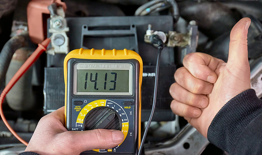
The easiest method to check the alternator is by measuring the voltage at the battery terminals when the engine is running.
- Start your Voyager.
- Connect the black cable of the multimeter to negative terminal of the battery, and the red cable to the positive terminal.
- The voltage should be between 13.5 and 14.8 volts with the engine running.
- Switch on the accessories in your Voyager, for example, headlights, AC fan at full speed, and interior lights.
- The voltage should remain around 14 volts. If it drops and remain below 13.5 volts, it indicates a problem with the current supply from the alternator.
- If the voltage drops below 12 volts with the engine running and the accessories turned on, it means the current supply from the alternator is completely cut off and all the electronics are solely powered by the battery.
Can you drive Voyager with a bad alternator?
Yes, you can drive your Voyager with a bad alternator, but only for a short distance. The battery charge will go down as you drive since all the on-board electronic controllers and accessories are now solely powered by the battery. When the battery charge gets too low the engine will shut down, and you will be stranded.
Recommended video
2. Poor ground connection
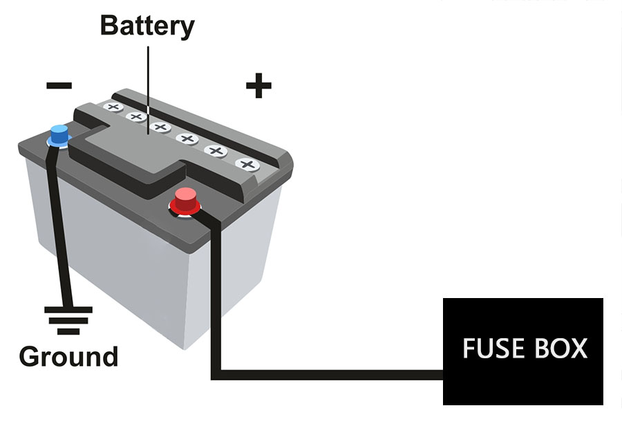
What is a ground connection.
The negative terminal of the battery is connected to the body/chassis of Voyager, called a ground connection. The engine also requires a ground connection to function, but the way the engine is mounted, it does not allow the electric current to flow between the engine and the body (due to non-conductive rubber insulated engine mounts). For this purpose, a ground strap/wire is used to connect the engine and the chassis.
What happens when the ground connection goes bad?
If the ground connection of the chassis or the engine goes bad in your Voyager due to rust or corrosion, you will face all sorts of electrical issues, including battery light illuminating in the dashboard. The alternator relies on the ground connection of the engine to function properly. When the ground is bad, the current supply from the alternator will be reduced or may fluctuate. Additionally, in rare cases the contact between the engine block and the alternator can also go bad due to corrosion.
How to check if the ground connection is good?
You can check the quality of the ground connection in Voyager by doing a conductivity test between the negative terminal of the battery and the engine. Take a multimeter, change its settings to ohms symbol. Touch one probe to the negative terminal of the battery, and the other probe to any exposed metal part of the engine. The reading should be at or very close to zero ohms. Do the same between the negative terminal of the battery and exposed metal part of the alternator.
Inspect and clean the ground connections
If the conductivity test fails, check the condition of the ground connections in your Voyager. Inspect the connectors of the ground cables (battery to body, body to engine) for any signs of rust or corrosion. Clean the contacts with a sandpaper or wire brush. You may also have to remove the alternator and clean the ground contact area on the alternator and on the engine block.
3. Poor battery connection
It is possible the alternator in your Chrysler Voyager is working properly, but the current flow is interrupted due to a loose electrical connection, a damaged wire, or corrosion on the battery terminals.
Corrosion on battery terminals
Battery corrosion is a fairy common problem (except in AGM batteries), especially if the installed battery is more than 2 years old. Corrosion occurs when the battery acid reacts with the metal terminals which can lead to loss of contact and reduced current flow. If there isn’t enough current flow, the battery will not be charged properly, and may cause engine starting problems.
Check battery terminals
To know if your Voyager charging system problems are from dirty battery terminals, you need to investigate them. Lift the plastic covers over the terminals and check for any signs of corrosion. If you discover white deposits or silvery-green deposits, but no further cracks or damage, you may not have to replace the battery or the alternator, just clean the battery terminals.

Clean the battery terminals
Quick cleaning: There is a neat little trick with which you can clean corrosion on the battery terminals of your Voyager in under a minute. Pour hot boiling water over the corroded terminals and the corrosion will just melt away. Do one terminal at a time and don’t let water puddle on the top of the battery touch both terminals at the same time, this can short the battery.
Thorough cleaning: To thoroughly clean the battery in your Chrysler Voyager, you have to remove the terminal cables first, which requires no special knowledge, just a little concentration, as the order is very important. First remove the black cable from the negative terminal using a wrench or a plier. Next you can unplug the red positive terminal cable. Be careful not to touch both terminals with your metal tool, it will be one expensive mistake. Once the battery has been removed from the circuit, you can start cleaning the corroded battery with sandpaper or wire brush. After cleaning, reconnect the cables in reverse order, positive first, then negative.
4. Slipping serpentine belt
The serpentine belt, also known as accessory belt or drive belt, transfers the power from the engine to other components like the alternator and the AC compressor, that are essential for normal operation of your Chrysler Voyager.
If the serpentine belt is damaged or becomes loose, or if the alternator pulley develops a defect, it can cause the belt to slip. This can cause the alternator to spin slower or inconsistently and the electricity production is degraded. When the on-board diagnostic system detects low voltage from the alternator, the battery symbol light comes on in the instrument cluster of Voyager.
Symptoms of bad serpentine belt
The most common sign of bad serpentine belt in Voyager is squealing noise from the engine compartment. Another prominent sign is visible cracks on the ribbed part of the belt. A slipping accessory belt can also cause burning smell.

Sound of a slipping serpentine belt
If the serpentine belt is found to be defective, it must be replaced. Keep in mind that a slipping belt is not always defective, it can slip due to a number of reasons, including due to a bad tensioner pulley or any other pulley.
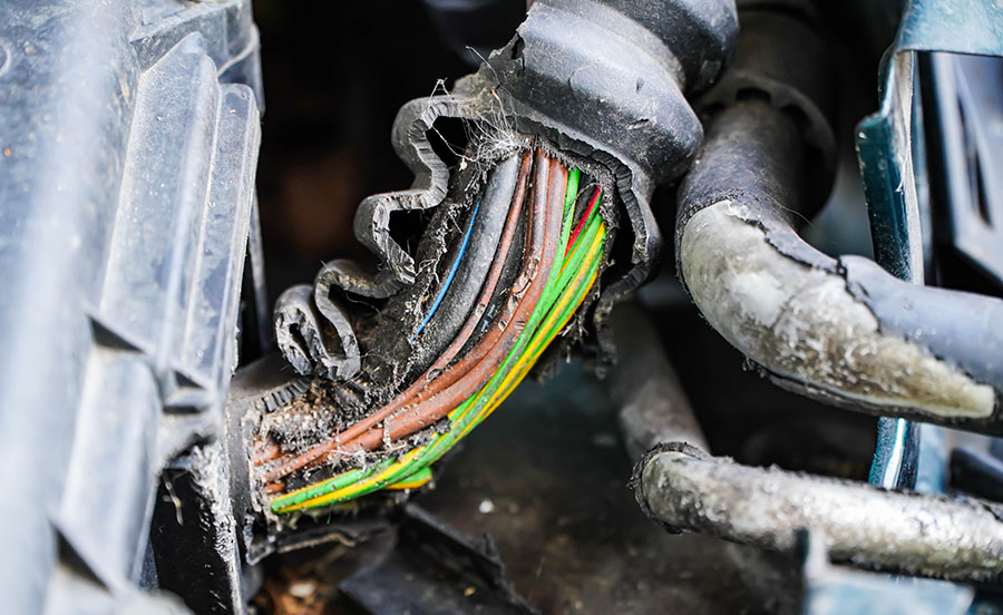
5. Rodent damage
If rodents like rats, mice, or squirrels have chewed up the cables for the alternator, it can cause the battery light to turn on in Voyager. Look for any signs of bite marks in the engine compartment, and examine all the cables for the alternator. If any cable has been damaged, replace it with a new one.
How to reset the battery light
Fix the issue.
Resetting the battery light in Voyager without solving the underlying issue may not help, as the warning light will turn back on when the system again detects the fault. The light should disappear automatically after fixing the issue. If it doesn’t turn off immediately, driving your vehicle for a few miles should help.
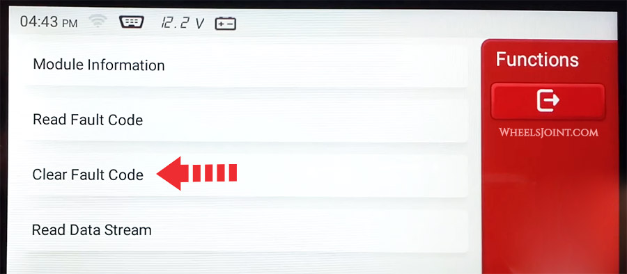
OBDII scanner method
The proper way to reset the battery light in Voyager is by clearing the codes with an OBDII scanner. If the warning light doesn’t turn off automatically after fixing the issue, you will have to do it manually by connecting a diagnostic device and then deleting all the error codes related to the charging system.
Disconnect the battery
If you don’t have a diagnostic device, it may be possible to reset the battery light in Voyager by disconnecting the battery for a few minutes. Remove the cable from the negative terminal of the battery first, then from the positive terminal. With the battery disconnected, press the horn button a few times and turn on the headlights to drain out all the residual electricity from the system. After about 15 minutes, reconnect the battery in reverse order: positive cable first, then negative cable.
Use OBD2 scanner for diagnosis
Since Chrysler Voyager is equipped with on-board diagnostics (OBD), a fault diagnosis can provide initial indications of where the malfunction is located.
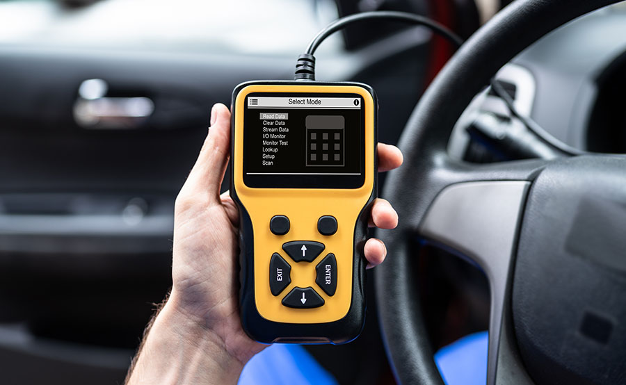
To begin troubleshooting, you must first connect the diagnostic tool to your Voyager. The OBDII connector is usually located under the dashboard. With the tool connected, turn on the ignition. Most diagnostic devices then ask for some information about the vehicle. It is important that you enter this 100% correctly, otherwise the result of the search may be inaccurate. In addition to the vehicle make, model, and engine type, you usually also have to type in the Vehicle Identification Number (VIN). Since some OBD codes are manufacturer-specific, the scanner will be able to give you more accurate information if you enter more details about your Voyager.
When the battery light comes on in your Chrysler Voyager, you should always start with testing the voltage at the battery when the engine is running. If the voltage test fails, then move on to testing the alternator and its electrical connections.
In any case, it is advisable for laypersons to visit a workshop. A professional mechanic can swiftly diagnose the charging system issue for you.

- SEAT Leon bad gas mileage causes and how to improve it
- Audi S5 key fob not working – causes and how to fix it
- Mercedes-Benz CLS bad gas mileage causes and how to improve it
- Kia Stonic dirty cabin air filter symptoms, when to replace
- Subaru WRX clogged catalytic converter symptoms, causes, and diagnosis
- Nissan Cube AC not cooling – causes and diagnosis
- Range Rover Evoque low AC refrigerant symptoms, how to recharge
- Toyota Verso uneven tire wear causes
- Dodge Challenger won’t start – causes and how to fix it
- Infiniti QX50 bad wheel speed sensor symptoms – how to diagnose
- Buick Lucerne low tire pressure warning light causes, how to reset
- Toyota Harrier check engine light is on – causes and how to reset
- Mercedes-Benz C-Class AC blowing hot air – causes and how to fix it
- Saturn Vue makes humming noise at high speeds – causes and how to fix it
- Mitsubishi Triton Android Auto not working – causes and how to fix it
- Cadillac XT4 bad alternator symptoms, how to check voltage
- Genesis GV80 key fob won’t lock or unlock the doors
- Jaguar F-PACE AC smells bad – causes and diagnosis
- Hyundai Palisade uneven tire wear causes
- Subaru WRX dead battery symptoms, causes, and how to jump start
Car Insurance
Home & renters insurance, car repair estimates, read car content, jerry data & research, what you should know about the chrysler voyager battery draining problem, what causes the chrysler voyager battery draining problem, how to fix the chrysler voyager’s battery draining problem, how to save money on chrysler insurance.
- Refer to your owner’s manual to figure out where your vehicle’s battery is.
- Turn your engine off .
- Using a wrench, loosen the bolt holding the (-) black cable . Then, remove the cable by twisting and pulling.
- Repeat the previous step to remove the (+) red cable .
- Remove the battery with a wrench or ratchet. You can do this by locating the clamp that holds your battery in place.
- Install the new battery by reversing the order of these steps, and you’re done!
- Parasitic draw (also known as parasitic drain) is when another electrical component in your car continually sucks power from your battery, even when the engine is turned off. This could be the cause of your problem.
- Often, a faulty alternator can create battery issues. If your alternator is to blame, you may need to repair or replace it.
- Corroded battery cables and terminals can affect the operation of your battery. Check to make sure everything is hooked up properly and for any signs of damage.
“When using Jerry , I just put in a bit of information, and they found lots of different quotes for me. I was paying $305 a month for 2 brand-new cars, but now I’m paying $150 a month for both with full coverage!” —Robin U.
Are you overpaying for your car insurance?

What You Should Know About the Dodge Ram Battery Draining Problem

What You Should Know About the Honda Civic Battery Draining Problem

What You Should Know About the 2017 Ford Fusion Battery Draining Problem
Read advice from car experts at jerry.

How to Replace Power Steering Fluid For a 2007 BMW 328i

The 5 Best Auto Shops in Nashville

What Are CV Joints on a Car–and When Do I Replace Them?

Browse Questions from Car Experts
How do you play music through bluetooth in a 2007 infiniti m35.

Where are the best places to live in Stockton?

How long does a DUI stay on your driving record in Texas?

Browse More Content
Insurance resources.
- Is Jerry Legitimate?
- Types of Car Insurance
- Car Loan Payment Fluctuations
- Buying a Car With No Credit
- How to Lower Insurance Premiums
- Bad Insurance Decisions
- Why is Car Insurance so Expensive?
- Buying a Used Car
- Adding a Name to a Car Title
- Removing a Name From a Car Title
Insurance for Your Car
- Hyundai Accent Insurance Cost
- Lincoln Ls Insurance Cost
- Bmw M5 Insurance Cost
- Audi Rs5 Insurance Cost
- Pontiac Vibe Insurance Cost
Insurance in Your State
Insurance in your city.
- Zachary LA Insurance
- Norcross GA Insurance
- Centereach NY Insurance
- Hermitage PA Insurance
- Cantonment FL Insurance
Easiest way to compare and buy car insurance
Car insurance by make, car insurance by model, car insurance by state, car insurance by city, car loan by make, car insurance by company, car loan by state, car repair by service.

auxiliary battery location CHRYSLER VOYAGER 2021 Owners Manual
Page 7 of 348.

CHRYSLER Owners Manuals
- 2017 CHRYSLER PACIFICA HYBRID 2.G Owners Manual
- 2012 CHRYSLER 300 2.G Owners Manual
- 2010 CHRYSLER SEBRING CONVERTIBLE 3.G Owners Manual
- 2008 CHRYSLER 300 SRT 1.G Owners Manual
- 2023 CHRYSLER VOYAGER Owners Manual
- 2013 CHRYSLER 200 CONVERTIBLE 1.G Owners Manual
- 2012 CHRYSLER 200 CONVERTIBLE 1.G Owners Manual
- 2002 CHRYSLER CARAVAN Owners Manual
- 2018 CHRYSLER 300 Owners Manual
- 2011 CHRYSLER 300 C 2.G Owners Manual
- 2022 CHRYSLER PACIFICA Owners Manual
View, print and download for free: auxiliary battery location - CHRYSLER VOYAGER 2021 Owners Manual, 348 Pages, PDF Size: 18.73 MB. Search in CHRYSLER VOYAGER 2021 Owners Manual online. CarManualsOnline.info is the largest online database of car user manuals. CHRYSLER VOYAGER 2021 Owners Manual PDF Download. 5 UCONNECT MODES ............................................. 159 Steering Wheel Audio Controls ................... 159 Radio Mode ........................
All product names, logos, and brands are property of their respective owners.
Privacy Policy | About Us & Contact

FREE SHIPPING on most orders of $35+ & FREE PICKUP IN STORE
2020 Chrysler Voyager
2020 Chrysler Voyager - Batteries
- Battery - Best Fit
- Battery - Optional
- Motorcraft Tested Tough MAX
- Odyssey Extreme
- Optima YellowTop
- Super Start Extreme
- Super Start Platinum
Group Size (BCI)
Cold cranking amps (cca), cranking amps (ca), reserve capacity (min), battery type.
- Standard Flooded
Terminal Type
Positive terminal location, length (in).
- 10-7/8 Inch
- 12-5/16 Inch
- 12-3/8 Inch
- 12-7/16 Inch
- 3-7/16 Inch
- 6-13/16 Inch
- 6-15/16 Inch
Height (in)
- 5-11/16 Inch
Super Start Platinum Group Size 400 Top Post Auxiliary Battery
Super start platinum group size 48 top post battery, super start platinum group size 94r top post battery, super start extreme group size 94r top post battery, acdelco top post battery, optima yellow top post battery, learn when it's time to replace a car battery.
A car battery stores energy that is produced by the alternator and helps start your car. The battery's stored energy also helps you use electrical accessories while the vehicle is not running, like the radio, lights, power outlets, and more. Car batteries wear out over time from exposure to high temperatures, corrosion, or a lack of battery maintenance. When automotive batteries begin to fail, they may no longer hold a sufficient charge to start the vehicle. If you notice the engine cranking slowly or taking longer than usual to turn over, it might be time to replace your battery. If you see abnormal amounts of corrosion around the posts or even the battery casing itself, your battery case may be leaking, and the battery should also be replaced. A bad car battery can cause a slow-turning engine, inconsistent or hard starts, or your vehicle's accessories or sound system may not operate when the engine is not running. You can find batteries for your car, truck, or SUV, as well as golf cart batteries, heavy-duty vehicle batteries, lawnmower batteries, and more. If you aren't sure of your battery's condition, or if you need to diagnose a problem with your starting system, take advantage of our free battery testing service. Battery testing can help you determine the health of your battery, and is a great idea before the seasons change to ensure your battery is up to the challenge this summer or winter. If you determine you need a new automotive battery but are unsure where to start, check out our helpful guide on how to choose a car battery . Make a confident repair with a new car battery, replacement battery cables, and much more from O'Reilly Auto Parts. For step-by-step instructions on your next project, visit our How-To Hub for content including how to install a car battery , how to replace a motorcycle battery , and much more. Keep your vehicle or lawn and garden equipment performing their best with the right parts, tools, and resources from O'Reilly Auto Parts.
Auto Genius
Chrysler voyager (2008 – 2020) – fuse box diagram.
Year of production: 2008, 2009, 2010, 2011, 2012, 2013, 2014, 2015, 2016, 2017, 2018, 2019, 2020
Engine compartment fuse box

WARNING: Terminal and harness assignments for individual connectors will vary depending on vehicle equipment level, model, and market.

- Visit Our Blog about Russia to know more about Russian sights, history
- Check out our Russian cities and regions guides
- Follow us on Twitter and Facebook to better understand Russia
- Info about getting Russian visa , the main airports , how to rent an apartment
- Our Expert answers your questions about Russia, some tips about sending flowers

Russian regions
- Belgorod oblast
- Bryansk oblast
- Ivanovo oblast
- Kaluga oblast
- Kostroma oblast
- Kursk oblast
- Lipetsk oblast
- Moskovskaya oblast
- Sergiev Posad
- Orlovskaya oblast
- Ryazan oblast
- Smolensk oblast
- Tambov oblast
- Tula oblast
- Tver oblast
- Vladimir oblast
- Voronezh oblast
- Yaroslavl oblast
- Map of Russia
- All cities and regions
- Blog about Russia
- News from Russia
- How to get a visa
- Flights to Russia
- Russian hotels
- Renting apartments
- Russian currency
- FIFA World Cup 2018
- Submit an article
- Flowers to Russia
- Ask our Expert
Podolsk city, Russia
The city of Moskovskaya oblast .
Podolsk - Overview
Podolsk is a city in Russia standing on the banks of the Pakhra River, about 37 km from the center of Moscow, 15 km from the Moscow Ring Road. It is one of the largest satellite cities of Moscow (the second after Balashikha), a large industrial and cultural center of Moskovskaya oblast.
The population of Podolsk is about 309,600 (2022), the area - 40 sq. km.
The phone code - +7 4967, the postal codes - 142100-142134.
Podolsk city flag
Podolsk city coat of arms.

Podolsk city map, Russia
Podolsk city latest news and posts from our blog:.
4 June, 2016 / Church of Our Lady (Znamenskaya) in Dubrovitsy .
14 May, 2015 / Church of the Sign of Our Lady in Dubrovitsy .
29 October, 2013 / Unique Baroque Church in the Dubrovitsy Estate .
History of Podolsk
Podol was first mentioned in written sources as a village in 1606. It became a town by the Empress Catherine’s the Great order in 1781. The population of the town was 856 people. In the 18th century, the first stone buildings appeared in the town.
The main occupation of the inhabitants was mining of rubble and white stone, from which, for example, the famous Znamenskaya Church in Dubrovitsy was built. In 1781, Podolsk received a coat of arms with two golden pickaxes symbolizing the main occupation of the local residents.
In September 1812, the town was occupied by the French troops during the French Invasion of Russia. The Trinity Church, located in the center of the present city, was erected in memory of this event.
More Historical Facts…
The development of Podolsk was promoted by construction of the State Warsaw (Brest-Lithuanian) Highway in 1844-1847. In 1866, Moscow-Kursk Railway came to Podolsk, it favored the development of the local industry. In 1875, a cement-producing plant was opened (in 1913, cement made about 95% of all the freight taken from Podolsk).
In 1900, the American company “Zinger” began the construction of their plant in Podolsk, the first in the Russian Empire. Production of sewing machines began in 1902. In November 1918, the plant was nationalized by the Soviet power and production stopped. The first Soviet sewing-machines were produced only in 1924.
During the years of the Civil War, there was a significant reduction in the town’s population. In 1920, the population of Podolsk was about 12,000 people. By 1939, due to intensive industrial development, the city’s population reached 72,000 people. In the 1950s, industrial development continued. In 1979, the population of Podolsk was 201,700 people. It became the first city of the Moscow region (Moscow is not part of it) with a population of more than 200 thousand people.
Streets of Podolsk

Lenin Avenue in Podolsk
Author: Alex N. Wild

Podolsk architecture

Podolsk - a city of contrasts
Podolsk - Features
The climate is temperate continental with relatively cold winter (early November - end of March) and warm humid summer (mid-May - early September). The average temperature in January is minus 9.4 degrees Celsius, in July - plus 18.4 degrees Celsius.
Podolsk is one of the largest industrial centers in the Moscow region. There are over 50 large and medium-sized industrial enterprises on the territory of the city. Besides, Podolsk is an important scientific center. There are several research institutions engaged mainly in nuclear machine-building and nuclear research.
Moscow - Kharkiv - Sevastopol railway passes through Podolsk. The federal highway M2 “Crimea” runs about 1 km east of Podolsk.
Attractions of Podolsk
There are a lot of monuments and memorial boards in Podolsk. The most interesting are the architectural and sculpture ensemble built in memory of World War II (Slavy Square) and the monument-obelisk to Miloradovich grenadiers who died in the Podolsk land in 1812 (Sobornaya Square, in front of the Trinity Cathedral).
The former Ivanovskoye estate and Dubrovitsy manor ensemble are also one of the main attractions of Podolsk.
- Podolsk Museum of Local Lore: the main building (Sovetskaya Square, 7), the branch of the museum in Ivanovskoye Estate (Parkovaya Street, 1);
- The Historical and Memorial Museum-Reserve “Podolye” (Lenina Avenue, 47);
- The Federal Museum of Professional Education (Parkovaya Street, 1);
- Podolsk Showroom (Lenina Avenue, 113/62).
- Podolsk Drama Theater PDK Drama (Pochtovaya Street, 8);
- “Vecherniy Zvon” (“Evening Bells”) Theater (Sverdlova Street, 38).
There are several Orthodox churches in the city. The Trinity (Troitsky) Cathedral (1819-1823) is the most famous. It was built in honor of the victory of the Russian Empire in the Russian-French War of 1812. During the Soviet regime, it was the only cathedral in the Moscow region open for visiting.
The Resurrection Church in Krasnaya Street is one of the oldest churches in Podolsk (first mentioned in 1627-1628).
Podolsk city of Russia photos
Pictures of podolsk.

The bridge across the river in Podolsk

The clock tower in the center of Podolsk

Trinity Cathedral in Podolsk
Dubrovitsy manor ensemble located near Podolsk

Dubrovitsy is a very beautiful place

The main building of Dubrovitsy mansion

Znamenskaya Church in Dubrovitsy
- Currently 2.94/5
Rating: 2.9 /5 (181 votes cast)
COMMENTS
Search: ( hood release, dead battery open trunk, climate settings, headlight aiming, turn signal bulb, ESP inoperative) View, print and download for free: battery location - CHRYSLER VOYAGER 2021 User Guide, 348 Pages, PDF Size: 18.73 MB. Search in CHRYSLER VOYAGER 2021 User Guide online.
How to replace the battery in a Chrysler Town & Country, Dodge Grand Caravan, Volkswagen Routan or a Lancia Voyager.
Chrysler Voyager - (SsmIntrigue / Wikipedia) The most common symptoms of dead battery in Chrysler Voyager are slow engine crank, no start, dim lights, flickering dashboard lights and clicking noises when trying to start the engine. The most common causes of dead battery in Voyager are internal degradation of the battery due to old age, and ...
Page 335 of 348. View, print and download for free: battery location - CHRYSLER VOYAGER 2021 Owners Manual, 348 Pages, PDF Size: 18.73 MB. Search in CHRYSLER VOYAGER 2021 Owners Manual online. CarManualsOnline.info is the largest online database of car user manuals.
Duralast Platinum AGM Battery BCI Group Size 48 760 CCA H6-AGM. Part # H6-AGM. SKU # 319460. Year Warranty. Check if this fits your Chrysler Voyager. Select store. for pickup availability. Standard Delivery by Apr. 23 - 24. Add TO CART.
Page 1 2023 VOYAGER O W N E R ' S M A N U A L... Page 2 ROADSIDE ASSISTANCE HOURS, DAYS A WEEK AT YOUR SERVICE. 1-800-521-2779 CALL OR VISIT CHRYSLER.RSAHELP.COM (USA) 1-800-363-4869 CALL OR VISIT FCA.ROADSIDEAID.COM (CANADA) SERVICES: Flat Tire Service, Out Of Gas/Fuel Delivery, Battery Jump Assistance, Lockout Service and Towing Service ...
Connect the black cable of the multimeter to negative terminal of the battery, and the red cable to the positive terminal. The voltage should be between 13.5 and 14.8 volts with the engine running. Switch on the accessories in your Voyager, for example, headlights, AC fan at full speed, and interior lights.
Equip cars, trucks & SUVs with 2021 Chrysler Voyager Battery from AutoZone. Get Yours Today! We have the best products at the right price. ... Positive Terminal Location: Top RightWidth: 6.94inBCI Group Size: 94RHeight: 7.5inNegative Terminal Location: Top LeftReserve Capacity Minutes at 25 Amp Load: 140minVoltage: 12.0VDC.
2021 Chrysler Voyager Battery. Your 2021 Chrysler Voyager battery will generally last between 3 to 5 years, but that can alter heavily depending on weather conditions battery size, type of battery, and driving habits. Even still, just because your battery isn't completely dead, doesn't express it's operating at optimal levels.
Updated on Jan 30, 2024. Table of Contents. The Chrysler Voyager battery draining problem could be caused by several different factors, including a parasitic draw, corroded battery terminals or damaged cables, a faulty alternator, or an old battery. Diagnosing the issue is complex, but fixing it is relatively easy and affordable.
Page 7 of 348. View, print and download for free: auxiliary battery location - CHRYSLER VOYAGER 2021 Owners Manual, 348 Pages, PDF Size: 18.73 MB. Search in CHRYSLER VOYAGER 2021 Owners Manual online. CarManualsOnline.info is the largest online database of car user manuals.
Shop for the best Battery - Best Fit for your 2020 Chrysler Voyager, and you can place your order online and pick up for free at your local O'Reilly Auto Parts. ... 2020 Chrysler Voyager - Battery - Best Fit Search Results. Filter By ... Professional Installation Recommended; CCA: 800; CA: 920; RC: 140; AGM; Without Start/Stop; Battery Located ...
Shop for the best Batteries for your 2020 Chrysler Voyager, and you can place your order online and pick up for free at your local O'Reilly Auto Parts. ... Professional Installation Recommended; CCA: 790; CA: 970; RC: 140; Without Start/Stop; Battery Located In Engine Compartment. 3 Year Limited Warranty. Battery Type: Standard Flooded. Height ...
Chrysler Voyager - fuse box - diagram engine compartment. Chrysler Voyager - fuse box - diagram engine ... Trailer Lighting, Front Fog Lamps, Intelligent Battery Sensor (IBS) 3: 20 '12-'20: Front/Rear Axle Locker ('12-'16), Vacuum Pump Motor: 4: 10 '08-'15: Trailer Tow: 5: 25: Inverter: 6: 20: Power Outlet No.1, Cigar ...
In this video I'll be replacing the auxiliary battery in a 2017 Chrysler Pacifica. The van recently experienced a no-start due to the battery being almost fu...
Equip cars, trucks & SUVs with 2022 Chrysler Voyager Battery from AutoZone. Get Yours Today! We have the best products at the right price. ... Positive Terminal Location: Top RightAmp Hour: 74AhReserve Capacity: 120minTerminal Type: SAE - Type ANegative Terminal Location: Top LeftEN Group Size: LN3Height: 7.5in
Negative Terminal Location: Top Left FrontPositive Terminal Location: Top Right FrontCold Cranking Amperage: 720ALength: 10.937inHeight: 7.5inTerminal Type: SAE - Type ABCI Group Size: 48Width: 6.875in. About 2020 Chrysler Voyager Car Battery. ... 2020 Chrysler Voyager Battery Size
It is one of the largest satellite cities of Moscow (the second after Balashikha), a large industrial and cultural center of Moskovskaya oblast. The population of Podolsk is about 309,600 (2022), the area - 40 sq. km. The phone code - +7 4967, the postal codes - 142100-142134.
Rome2Rio makes travelling from Moscow to Podolsk easy. Rome2Rio is a door-to-door travel information and booking engine, helping you get to and from any location in the world. Find all the transport options for your trip from Moscow to Podolsk right here. Rome2Rio displays up to date schedules, route maps, journey times and estimated fares from relevant transport operators, ensuring you can ...
Equip cars, trucks & SUVs with 2023 Chrysler Voyager Battery from AutoZone. Get Yours Today! We have the best products at the right price. ... Positive Terminal Location: Top LeftReserve Capacity: 0minLength: 5.88inWidth: 3.44inAmp Hour: 14AhNegative Terminal Location: Top RightHeight: 5.75inCranking Amperage: 250A
Equip cars, trucks & SUVs with 2020 Chrysler Voyager Auxiliary Battery from AutoZone. Get Yours Today! We have the best products at the right price. ... Positive Terminal Location: Top LeftAmp Hour: 14AhNegative Terminal Location: Top RightReserve Capacity: 0minLength: 5.88inWidth: 3.44inHeight: 5.75inCranking Amperage: 250A