Overload or Thermal Protection (ANSI 49)
Introduction
Overload or thermal protection protects all types of motor applications against overload currents.
Operating Principle
Overload or thermal protection is I 2 t IDMT (Inverse Definite Minimum Time):
o It incorporates the motor thermal image function.
o It can be configured as the Ir pickup and as the trip class (Class).
Tripping curve:
Ir Pickup Setting Value
The overload or thermal protection pickup (Ir) is set by using a multi-position dial.
The default Ir pickup setting value is 0.4 x In (minimum dial value).
The overload or thermal protection tripping range is 1.05–1.20 x Ir according to IEC/EN 60947-4-1 standard.
The following table shows the preset values of the adjustment dial Ir in amperes for each current rating In:
Trip Class Setting Value
The trip class (Class) is set by using an adjustment dial:
o Class 10 (default value)
The trip class corresponds to the value of the tripping time for a current of 7.2 x Ir according to IEC/EN 60947-4-1 standard.
The following table shows the value of the tripping time depending on the current in the load for all three classes:
The precision range is -20%, + 0%
Motor Thermal Image
The model representing heat rise and cooling in a motor load is constructed according to the algorithm for calculating the thermal demand, taking account of the iron and copper losses.
The following figure represents the limit curves for the iron and copper components calculated for class 20:
Thermal Memory
The trip unit uses a thermal memory function to protect the motor from overheating in case of low amplitude repetitive faults.
Electronic protection without thermal memory function does not protect against repetitive faults because the duration of each overload above the pickup setting is too short to cause tripping. However, each overload causes a temperature rise in the installation. The cumulative effect of successive overloads can overheat the system. The thermal memory function remembers and integrates the thermal heating caused by each pickup setting overrun. The thermal memory function remembers the thermal heating values for 20 minutes before or after tripping.
Example: Comparison of the heat rise calculation without thermal image (diagram A ) and with thermal image (diagram B ):
With thermal image, the trip unit adds the thermal effect of successive current pulses. Tripping occurs based on the actual thermal state of the motor.
Cooling Fan
The thermal image of the motor is calculated taking account of the fact that the motor is self-cooled (fan mounted on the shaft end).
DOCA0161EN-01
© 2020 Schneider Electric. All rights reserved.
- Site Search Search Posts Find A Forum Thread Number Threads by Name Search FAQs
- ENGINEERING.com
- Eng-Tips Forums
- Tek-Tips Forums

Join Eng-Tips ® Today!
Join your peers on the Internet's largest technical engineering professional community. It's easy to join and it's free.
Here's Why Members Love Eng-Tips Forums:
- Notification Of Responses To Questions
- Favorite Forums One Click Access
- Keyword Search Of All Posts, And More...
Register now while it's still free!
Already a member? Close this window and log in.
Join Us Close
Overload Relay – Definition, Types, and Principle
Overload relay is very common when we are dealing with electric motors. Why is that?
Electric motors are often used in equipment that include rotating parts. Because motors are often fairly costly, it’s critical to avoid them failing due to carrying more electric current than their rated amperage.
Ground faults (short-circuits in the motor windings or peripheral cables) can cause electrical overload, but jamming or inappropriate operation are more prevalent causes.
Every motor must be protected against all possible flaws in order to ensure long-term, safe operation and save time lost due to breakdown. Almost all industries rely on electric motors to regulate their processes and output. As a result, the engine must be made fail-safe.
Overload relays are one type of device that prevents a motor from being damaged by overloads and overcurrents. It’s found in motor control centers and motor starters, and it’s used with contactors .
What is Overload Protection?
Overload relay is one types of relays we will encounter one day.
Overload relay is mostly used as an overload protection. But what is overload protection?
An overload occurs when the motor consumes too much current. This may cause the motor to overheat, causing damage to the windings. As a result, it’s critical to protect the motor, motor branch circuit, and motor branch circuit components from overload.
Overload relays protect the motor, motor branch circuit, and motor branch circuit components from excessive heat caused by an overload. The motor starter includes overload relays (assembly of contactor plus overload relay).
They protect the motor by keeping an eye on the current going through the circuit.
If the current exceeds a preset limit for an extended length of time, the overload relay trips, activating an auxiliary contact that terminates the motor control circuit and de-energizes the contactor.
As a result, the motor’s power is turned off. The motor and motor circuit components do not overheat and become damaged when there is no power.
Overload relays can be manually reset, and some overload relays will reset themselves after a period of time. After that, the motor can be turned back on.
Overload Relay Definition
Overload relays are devices that protect electric motors from overloads and phase failure.
When the motor is overloaded, it detects this and terminates the power flow, preventing the motor from overheating and winding damage.
It can also protect the motor from phase loss/failures and phase imbalance, in addition to overloads. They’re usually referred to as OLR.
What is an overload, exactly?
An overload occurs when a motor draws a current that is greater than its rated value for an extended length of time.
It’s the most common problem, and it might cause the motor winding to overheat. As a result, a quick return to regular operation is critical.
Read also : basic direct current circuit
Overload Relay Parts
Aside from the bimetallic strip and contacts indicated in the working principle section, there are a few other components in an overload relay worth mentioning.
Observe the thermal overload relay below:
Input terminals L1, L2, and L3 are available. It can be mounted directly to the contactor. Terminals T1, T2, and T3 can be used to supply power to the motor.
Ampere range toggle
Over the overload relay, there is a rotary knob. The rated current of the motor can be set with this knob. The current can be adjusted between the supplied upper and lower limits. In the case of an electronic overload relay, there is also a knob for selecting the tripping class.
Reset button
The overload relay has a reset button that can be used to reset it after a trip and fault clearance.
Automatic-Manual reset mode
We can choose between manual and automatic reset of these relays after a journey using the manual/auto reset selection button. A remote reset of OLR is available if the device is set to auto.
Auxiliary contact
They come with two auxiliary contacts: one NO (97-98) and one NC (97-98). (95-96). The NO contact is used to signify a trip, whereas the NC contact is used to disconnect the contactor. NC contacts should be able to switch the contactor coil directly.
Testing button
The control wiring can be tested by pressing the test button.
Overload Relay Symbol
One thing you should know and understand is that every electrical component, element, and device have their symbol.
This symbol will make it easier to use when drawing, designing, and analyzing.
Observe the symbol of thermal overload relay below:
Terminals 1, 2, 3, 4, 5 and 6 are power terminals Terminals 95 and 96 are trip contacts Terminals 97 and 98 are signal contacts.
Overload Relay Connection Diagram
The overload relay connection diagram is given below, and the overload relay sign is represented by two opposite question marks.
Otherwise, the overload relay function is addressed using the ‘S’ symbol. Although there are many different types of overload relays on the market, the “bimetallic thermal overload relay” is the most commonly utilized.
This relay’s design incorporates two different types of metal strips, which can be interconnected and grow at various speeds when heated.
When this strip reaches a specific temperature, it can provide enough turns to break the circuit.
After a few seconds, the overload is identified when the flow to the motor exceeds the charge for the heater. The time of the relay exploration is used to classify overload relays into three sorts.
Overload relays for 10 seconds, 20 seconds, and 30 seconds can be found in the Class 10, Class 20, and Class 30 categories.
This relay’s key characteristic is that it prevents the engine from starting right away. The overload relay, for example, probes into the bimetallic relay, and the NC (normally closed) bimetallic connections release the circuit until the strip cools.
The motor will not start if any contactor tries to push the start switch to turn it off.
Principle of Overload Relay
The electro-thermal characteristics of a bimetallic strip are used to operate a thermal overload relay. It is wired into the motor circuit so that the current flows through the poles of the motor.
The current heats the bimetallic strip directly or indirectly, and it bends when the current flow surpasses the predetermined value.
They’re always used in tandem with contactors. When the bimetallic strips heat up, the trip contact opens, cutting off power to the contactor coil, de-energizing it and interrupting current flow to the motor.
The current flow through the OLR is always inversely proportional to the tripping time. As a result, the stronger the current flow, the faster it will trip.
A = Indirectly heated bimetal strips B = Trip slide C = Trip lever D = Contact lever E = Compensation bimetal strip
Thermal overload relays are thus described as current-dependent and inversely time-delayed relays.
Overload Relay Types
The following are the several types of overload relays:
- Bimetallic thermal overload relays
- Electronic overload relays
- Eutectic overload relays
- Solid state overload relays
Each of the above works on a somewhat different principle. Let’s have a look at it in the parts below.
Bimetallic Thermal Overload Relay: How it Works
A bimetallic thermal relay, as previously stated, relies on the heating properties of a bimetallic strip. The complete current to the motor flows through the OLR in the direct heating approach.
As a result, the current heats it up directly.
Indirect heating, on the other hand, keeps the bimetallic strip in close contact with the current-carrying wire inside the OLR. The conductor and, as a result, the bimetallic strip heats up when there is too much current flowing to the motor.
Because the conductor is insulated, no current can pass through the strip.
Electronic Overload Relay: How it Works
This is also known as solid state overload relays.
There is no bimetallic strip inside electronic overload relays. Instead, it detects the amount of current flowing to the motor using temperature sensors or current transformers. It protects you using microprocessor-based technologies.
PTC is used to sense temperature and to trip the circuit in the event of an overload fault. Current transformers and Hall effect sensors are included in some electronic overload relays, which directly sense the amount of current flowing.
The lack of a bimetallic strip in electronic OLR leads to low heat losses inside the relay, which is a major advantage over thermal OLR.
Electronic relays are also more accurate than thermal relays.
Electronic relays from some manufacturers come with a variety of characteristics, such as earth fault protection, motor stall protection, and so on.
Earth fault protection can also be achieved using CBCT on the secondary three phase windings.
Electronic overload relays are ideal for applications where motors must start and stop frequently.
They are built to sustain the motor starting current (which is normally 6 to 10 times the full load current) for a limited time (typically 15-30 seconds depending on the threshold of current).
Eutectic Overload Relay: How it Works
A heater winding, a mechanical mechanism for activating a tripping mechanism, and a eutectic alloy make up this sort of overload relay. An eutectic alloy is made up of two or more components that solidify or melt at a given temperature.
The eutectic alloy is housed in a tube in the overload relay, which is frequently used in conjunction with a spring-loaded ratchet wheel to trigger the tripping mechanism during overload operations.
The little heater winding conducts the motor current. The heater winding heats the eutectic alloy tube during the overload.
As a result of the heat, the alloy melts, releasing the ratchet wheel and allowing it to turn. The overload relay’s closed auxiliary contacts are opened as a result of this action.
After tripping, Eutectic overload relays can only be manually reset. This is commonly accomplished by pressing a reset button located on the relay’s cover.
The heating unit put on the relay is selected based on the motor’s full load current.
Overload Relay Trip Class
The trip class specifies how long it takes them to open the contactor during overloads.
Observe the table below from Schneider:
Class 10, Class 20, Class 30, and Class 5 are the most popular classifications. At 600 percent of full load current to the motor, the OLR trips in 10 seconds, 20 seconds, 30 seconds, and 5 seconds, respectively.
Class 10 and Class 20 are the most widely utilized. Motors generating high inertia loads are protected by Class 30 overload relays, while motors requiring very fast tripping are protected by Class 5 relays.
They are always utilized in conjunction with the circuit’s contactors. It is wired in series with the motor, allowing the electricity to flow freely through it.
The many methods of connectors for single-phase and three-phase motors are listed below.
Overload relays K1 and K1M are used. A single phase motor connection is shown in the first and second pictures, while a three phase motor connection is shown in the third.
Overload Relay Advantages
Overload protection relays come in a variety of shapes and sizes. Fuse, thermal relays, electromechanical relays, and electronic relays are examples.
Low-current devices, such as domestic appliances, are frequently protected by fuses.
High-current machinery, such as industrial motors, are protected by thermal, electromechanical, and electronic relays.
The following are the key advantages of relays:
1. PROTECTION THAT CAN BE RELIED ON When a high-current scenario arises owing to a ground fault, short circuit, phase failure, or mechanical jamming, overload relays turn off electricity to the motor. They’re a low-cost technique to reduce downtime while repairing or replacing motors that have failed due to excessive current.
2. MATCHING CONTRACTORS APPROPRIATELY Contractors carry the main circuit’s high operational currents. They contain built-in systems to prevent arcing caused by heavy motor current interruption. When contactors and thermal relays are appropriately matched, the result is a good motor starting circuits
3. STARTERS ARE SIMPLE TO USE. Manual motor starters are used to turn on and off motors. These electromechanical devices are simple to set up and reset once they have tripped.
4. MOUNTING KITS For several types of overload protection relays, application-specific mounting kits are provided.
To control their activation threshold, overload protection relays have adjustable current setting ranges. They can detect and defend against phase faults in addition to preventing electrical overload.
Because these relays are frequently used in hot situations, they have ambient temperature tolerances of up to 60 degrees Celsius.
Relays also include sealable automatic or manual resets to protect them from the hazardous conditions in which they work.
While not carrying an electrical current, relays have stop and test operations to ensure their operational integrity.
Overload Relay vs Circuit Breaker
What is the difference between an overload and a current that is too high?
A type of overcurrent is an overload. Overload is an overcurrent that is sustained within the boundaries of the equipment’s permitted current rating yet causes the equipment to overheat.
Overcurrent is usually instantaneous. A type of overcurrent is a short circuit.
What is an overload in a circuit, for example?
When you draw more electricity than a circuit can safely handle, you have an overload. Wiring, a breaker (or a fuse in older wiring systems), and gadgets make up a circuit (such as light fixtures, appliances, and anything plugged into an outlet).
Is overload protection provided by a circuit breaker in this case?
A circuit breaker is an electrical switch that operates automatically to safeguard an electrical circuit from harm caused by an overload or short circuit.
Its primary purpose is to stop current flow when a defect is identified.
What is an overload protection device, and how does it work?
When the current reaches a level that causes an excessive or dangerous temperature rise in conductors, an overcurrent protection device opens to protect the circuit.
Short-circuit or ground-fault current values, as well as overload circumstances, are detected by most overcurrent protection devices.
1. Why is the OLR tripped?
As previously stated, there are three key factors that lead to overload trips:
- The motor is overloaded.
- Loss of input phase
- Unbalanced phase.
Aside from this, various more security features may be available. This varies depending on the manufacturer.
2. How does overload relay protect from phase failures?
The current flowing through each pole of an overload relay to the motor remains constant during normal operation.
If one of the phases is disrupted, the current in the other two phases increases to 1.73 times its typical value.
As a result, the overload relay heats up and trips. Single phasing of the motor or phase loss are other terms for phase failure.
3. Is an overload relay able to protect from short circuits?
Short circuits are not protected by overload relays. Short circuit protection devices should always be utilized with them.
Otherwise, any short circuits in the motor could cause them to fail. Overloads, phase loss, and phase imbalance are all protected, but short circuits are not.
2 thoughts on “Overload Relay – Definition, Types, and Principle”
Thanks, these notes are very helpful for the people how learn electrical installation course or electrical engineering.
The information I have received is very helpful,you are doing an amazing job I can’t compare to any other,thank you very much.
Leave a Comment Cancel reply
Save my name, email, and website in this browser for the next time I comment.
Nema classes VS Ansi tripping curves
Home » Insights » UL and CSA Conformity » Nema classes VS Ansi tripping curves
Last edit: 16/05/2023
Overload relays typically operate on an inverse time curve where the tripping time becomes less as the current increases. They are rated by trip class. Trip class specifies the length of time it will take for the relay to open in an overload condition.
In Europe the shape of the overload relays tripping curves are defined by ANSI or IEEE standards. A few examples are: ANSI Extremely Inverse, Very Inverse, Inverse, Short Time Inverse; or IEEE Moderately Inverse, Very Inverse and Extremely Inverse.
In North America the NEMA Standard MG-1 defines 4 types of Classes as the most common: 5, 10, 20 & 30. Class 5, 10, 20 & 30 overload relays will trip within 5, 10, 20 & 30 seconds respectively at 600% of motor full load amps.
Class 5 is usually used for motors requiring extremely fast tripping.
Class 10 is commonly used to protect artificially cooled motors such as submersible pump motors of low thermal capacity.
Class 20 is usually sufficient for general purpose applications.
Class 30 is usually required for high inertial loads to help prevent nuisance tripping.
Core Competencies
- Get custom product tools and services
- Access training
- Manage support cases
- Create and manage your orders (authorised partners only)
Welcome to the Schneider Electric Website
Search FAQs
What is the meaning of trip class ( like class 10 ) in lrd overload relays., released for: schneider electric india.
Articles that might be helpful
Discuss this topic with experts
Start here!
Find answers now. Search for a solution on your own, or connect with one of our experts.
Contact Support
Reach out to our customer care team to receive more information, technical support, assistance with complaints and more.
Where to buy?
Easily find the nearest Schneider Electric distributor in your location.
Search topic-related frequently asked questions to find answers you need.
Contact Sales
Start your sales enquiry online and an expert will connect with you.
- Remember me Not recommended on shared computers
Forgot your password?
- Motor Protection / Failure
Overload Trip Class - What does it really mean?
By GGOSS , February 25, 2003 in Motor Protection / Failure
- Reply to this topic
- Start new topic
Recommended Posts
Quite often we here of applications in which the motor protection/overload relay 'trips' during motor starting. The remedial action taken by many when faced with this problem is to select and install a replacement overload relay, generally one that provides a higher 'Trip Class' setting, for example, Trip Class 20 in lieu of the standard Trip Class 10.
Note: The appears to be a general misconception in industry that Overload Trip Class relates directly to the starting time of a machine. This is not the case.
All due care must be taken when selecting a protection relay offering higher Trip Class, as this can result in under protection and subsequent failure of the motor.
To select an overload relay with a more suitable trip class, you must in the first instance obtain data relating to the motor’s thermal withstand capabilities. That is, you need to know how many seconds (from cold condition) the motor can the sustain Locked Rotor Current before it is compromised.
This information is readily available from most leading manufacturers of motors and is generally provided in one of two formats.
a) Specific values for Locked Rotor Current and maximum Locked Rotor Time (from 'cold condition' ) are given.

With this information available to you, you can refer to the tables given in IEC 60947 to identify the most appropriate Overload Trip Class. This is defined as the one that provides a trip curve as close as possible to but below the overload curve of the motor. Adopting this process will ensure nuisance tripping is minimised and that the motor is adequately protected at all times.
Note: If the above processes are adopted but the trip conditions continue, there are 4 possible causes.
1. The motor (and overload relay) are not given sufficient time to cool between starts.
2. Assuming reduced voltage start (star/delta, auto-transformer, primary resistance, soft start etc., the motor is not delivering torque sufficient to accelerate the connected load to speed. That is the starting current and starting time under RVS conditions exceeds that permissible by the overload curve.
3. A more advanced protection strategy such as motor thermal modelling may be required. Motor thermal modelling allows the user to 'match' the curves of the protection device to the connected motor. This is of particular advantage when the motors thermal withstand capabilities and the start condition (starting current and starting time) fall between two curves defined by standard overload trip classes.
4. The motor is simply too small for the application.
Put simply, the most appropriate protection strategy is the one that allows the motor to be fully utilised without nuisance tripping or fear of motor burn-out.
Link to comment
Share on other sites.
Mark Empson | administrator Skype Contact = markempson | phone +64 274 363 067 LMPForum | Power Factor | L M Photonics Ltd | Empson family | Advanced Motor Control Ltd | Pressure Transducers | Smart Relay | GSM Control | Mark Empson Website | AuCom | Soft Starters
Thanks for the comments Marke,
When I get a chance I'll scan the tables referred to in my previous post, and post them here. Hopefully that will make life a little easier for anyone interested in the subject.
- 7 months later...
The simple explanation is "class 10" will trip within 10 seconds of locked rotor condition. "Class 20" will trip within 20 seconds of locked rotor condition. "Class 10" should be the standard selection. If your application requires longer motor run up time you can use the "class 20".
In a separate but similar matter keep in mind overload selection per NEC is 125% of nameplate FLA (based on 1.15 SF and 40C temp rise). If you try this and your motor still can't start up you can go to a max of 140% of motor nameplate FLA(based on 1.15 SF and 40C temp rise).
Hello grobert
Welcome to the forum.
The LRC can vary considerably between motors, but will generally lie in the range of 600% to 900% of the rated full load current of the motor.
I believe that the quoted trip time are for a LRC in the 600 - 650% range.
Best regards,
Hello Grobert,
Without trying to offend in any way, the statement "If your application requires longer motor run up time you can use the "class 20" in your post of 9/10/03, is a general misconception often resulting in under-protection and subsequent failure of motors.
The very reason I started this thread was to provide an understanding of what 'trip class' actually means thus further assisting people with the selection of motors for the more difficult industrial applications and then the correct selection & set-up of overload relays.
If you believe the original post can be re-written to make it clearer/easier to understand, I would certainly appreciate your input and would be happy to do the necessary work.
Thanks & regards,
no offense taken.
If your application requires longer motor run up time you can use the "class 20" in your post of 9/10/03, is a general misconception often resulting in under-protection and
That quote was near verbatim from an explanation on class selection of adjustable overloads from a manufacturers book (Sprecher & Schuh). We are always told, and it is an NEC requirement, to follow manufacturer's documentation. As far as rewriting the original submittal it is apparent to me that you are more than qualified and I can offer no further technical information. I do have to wonder about the statement "resulting in under-protection " The whole point of doing anything other than a setting above 125% of motor nameplate FLA is if you have a situation that has been tried and failed to allow the motor to start up. You would use, for IEC components, class 10 set to the motor nameplate FLA first. Its trip characteristics would allow for the 115% over the face setting. There would be no reason to go further if your motor started up. However if needed, and the HP is not undersized for the work to be done, you are allowed to take steps. NEC allows for a maximum of 140% of nameplate FLA if you have tried the 125 and it would not allow startup. The values I am listing are for motors with a 1.15 service factor and minimum 40 temp rise in Celsius. Obviously you will be giving up some overload protection but you must do what is necessary to allow the motor to start up. The application should be, and I believe required to be, set up per NEC requirements. Upsizing class or OL face settings can only be done when that has been tried and failed to allow full starting. I appreciate the opportunity to discuss these matters with individuals such as yourself.
Great post worthy of considered & detailed response.
Let me start by saying INTERESTING! Having had a direct involvement with the S+S motor protection products since 1982, I am very surprised that THEY would make such a statement in their book. S+S established themselves as a leader in the field of electronic motor protection many years ago ie when they released their CET1 electronic motor protection relay. Now at CET5, the CET range has always offered a motor thermal modeling function, which, in essence is the next level up from adjustable trip class. Devices that offer the motor thermal modeling feature allow you to set a protection curve that most closely resembles the thermal withstand curve of the connected motor. This provides for maximum motor utilization (production) without fear of nuisance tripping or motor burnout.
If it could be put in relative terms, an overload relay providing adjustable trip class may provide curves for say trip classes 10 and 15, but the thermal withstand curve of the connected motor may fall somewhere between the two. If you set the overload to trip class 10, then you are in fact over-protecting the motor and not able to make full use it its thermal capacity. If you set to trip class 15, then you are under-protecting the motor (allowing it to operate beyond its thermal capacity) thus compromising its service life. A product that provides motor thermal modeling may allow you to set for example the equivalent of trip class 12 which as we know is not a valid trip class, but most suitable for the motor in this example.
In your post you make the comment “There would be no reason to go further if your motor started up”. That statement holds true for industrial applications that do not experience repeated transient overloads during normal operation (eg jaw crusher) and/or where restart capability is not a priority (eg long cool down time between starts). Being able to fully utilize the motors thermal capacity is essential in many applications and therefore we need to think beyond the starting function.
The next statement that I find interesting if not frightening is “NEC allows for a maximum of 140% of nameplate FLA if you have tried the 125 and it would not allow startup”. Man...this is scary stuff! The need to do this would not be necessary if one had reviewed the motor thermal curves and selected an overload relay with the correct trip class or installed a protection relat with programmable thermal model in the first instance. Irrespective of the selected curve, the ‘ultimate trip point’ of both would always be less than 1.15 times the face setting and therefore the motor would never be compromised. It would appear some updating of NEC is required!
Grobert, I too appreciate the opportunity to discuss these matters with individuals. Lets face it if we are not either contributing or learning then we're as good as dead!
PS: I have developed a powerpoint presentation that greatly assists to further explain the above and highlight the functional differences between overload relays with adjustable trip class and thermal modelling. Will discuss with Marke the possibility of posting a non-downloadable version on LMPhotonics. Not sure if that's possible but he seems to be able to achieve the impossible on occassions.
- 2 weeks later...
Hello Raka,
There is a possibility that a non-downloadable version will be added in future. Can't promise anything at this stage.
I will consult Marke and advise in due course.
- 3 weeks later...

Something worth noting in your excellent discussion of OL class issues. The Class number, i.e. 10, 20 30 etc., denotes the tripping time at 600% current, as previously pointed out. What most people don't know however is that that is only the MAXIMUM tripping time. A relay which trips earlier than the desired Class rating can still be labled at that class. For instance if, during testing, a Class 10 relay trips in 6 seconds, then 7 seconds, then 9 seconds, it is considered good as a Class 10 relay. As long as it never takes 11 seconds or more.
We did some extensive testing of both bimetal OLRs and electrnic OLRs from 20+ manufacturers for inclusion in one of our products. We found that most Bimetal relays tripped very early, as in 6-8 seconds, at 600%. Eutectic melting alloy relays were a little more consistant, but presented other problems for us. Most electronic OLRs were much more accurate and repeatable so that is what we ended up using.
Hello jraef,
You are absolutely correct, up until a few years ago all trip time references were made against an overload current of 6 x the face setting on the overload relay. More recently however that has been changed, the reference current now being 7.2 x FLC, most probably because the Locked Rotor Current of motors these days is much higher than in years gone by.
The problem with that however is that it has added a lot of confusion to what was once quite simple to comprehend. That is, whereas previously trip class 10 was defined as a trip within 10 seconds at 6 x FLC, it is now defined as a trip within 7 seconds at 7.2 x FLC. When you do the calculations however you will find the I2t is pretty much the same and therefore the protection performance is also the same.
That leads me to the second point which is to briefly outline the performance differences between electronic and bi-metalic overload relays. As you quite rightly stated in your post, tests conducted on several bi-metalic overload relays of different manufacture will show that they trip in much less than 10 seconds and that there is no consistency between brands. Multiple tests on a single bi-metalic overload relay will also show an inconsistency in trip time for the same reference or overload current. A difference of +/- 2 seconds between trials is certainly not unheard of, and I guess the overall performance would be very much dependant upon the level of ambient temperature compensation and a number of other design and material tolerance factors.
This inconsistency in tripping time was also very noticeable on earlier electronic overload relays which made us of RC networks to emulate the transfer of heat into the motor windings (copper temperature), the transfer of heat from the windings to the frame (iron temperature) and finally the transfer of heat to the frame to the atmosphere which needless to say is different for both the run and standstill conditions. You can image component tolerances coming into play here generating inconsistencies. You can also imaging that it would be difficult if not impossible to produce an I2t curve using discrete components.
The more recent electronic motor overload relays are digital by design. Their trip curves are accurate and repeatable and follow a fixed I2t characteristic, thus making it possible to calculate the tripping time at any level of overload current, from a cold condition.
For the above reasons, where $ permit, I will always offer/use electronic overload relays over bi-metalic ones. However with the falling price of electronics, I don't think it will be too much longer (3 - 5 years) before bi-metalic relays become obsolete.
You are right about that. We were disappointed in the lack of flexibility we found available in SSOLs, so we are making our own. Because of the microprocesser power available, our engineers went crazy and put in lots of extra features etc., which makes it more expensive than a bimetal (naturally!). Now we are starting to work on a stripped down version which will rival their current selling price. Knowing what I know about the cost of manufacturing electro-mechanical devices like that, they will probably respond by lowering prices even further, but at least the marketplace benefits. In the long run, the inaccuracies of bimetal OLRs will be relegated to the "how cheap can I get away with and still meet minimum standards" market, which will ALWAYS exist.

× Pasted as rich text. Paste as plain text instead
Only 75 emoji are allowed.
× Your link has been automatically embedded. Display as a link instead
× Your previous content has been restored. Clear editor
× You cannot paste images directly. Upload or insert images from URL.
- Submit Reply
Who's Online (See full list)
- There are no registered users currently online
Tell a friend
- Existing user? Sign In
- Online Users
- Leaderboard
- All Activity
- Create New...
- Supplemental and Obsolescence Digest 178
Section 16: NEMA and Definite Purpose Contactors and Starters
- NEMA and Definite Purpose Contactors and Starters
- Manual Starters, Type F—Fractional Horsepower
- Manual Switches, 30 A—Type K
- Type F and K—Approximate Dimensions
- Approximate Dimensions—Type F and K
- Manual Starters, Type M and T—Integral Horsepower
- Accessories, Modifications, and Replacement Parts
- TeSys™ Ultra Starter Components
- Catalog Numbering System: T02 and T36
- Non-Reversing Contactors
- Reversing Contactors
- Non-Reversing Starters
- Reversing Starters
- Accessories
- Replacement Parts
- TeSys™ N Dimensions
- Catalog Numbering System
- Contactors, Type S
- Starters, Type S
- Application Data
Approximate Dimensions
- NEMA Style Contactors, 600 V
- NEMA Style Contactors, 1500 V
- NEMA Style Starters, 600 V
- Ready to Install NEMA Combination Motor Starters
- Non-Reversing
- Multipole Lighting Contactors, Type L and LX
- Multipole Lighting Contactors, Type S
- Combination Lighting Contactors, Type S
- Night-Master™ Combination Lighting Contactors
- Factory Modifications (Forms)
- Field Modifications
- Types DP, DPA
- Types DPS and H through M
- Full Voltage, Type SS, XS
- Full Voltage, Style S2
- Replacement Parts and Dimensions
- Full Voltage
- Reversing Hoist, Type DPR
- Melting Alloy Overload Relay
Motor Logic™ Solid-State Overload Relay
- TeSys™ T Motor Management System
- Bimetallic Overload Relay
- External Reset Mechanisms
- NEMA 3R, 4, 4X, and 12
- NEMA 1 and Flush Mounting
- NEMA Types 1, 4, 12/3R, and Oversize
- Full Voltage Contactors, Starters, and Overload Relays
- For Full Voltage Contactors & Starters
- Replacement Magnet Coils
- Contactor and Starter Replacement Part Kits
- Starter Accessories
- Cover-Mounted Control Units
- Auxiliary Contacts
- Mechanical Interlocks
- Fuse Block Replacement Parts Kits
- Thermal Unit Selection
Class 9065 / Refer to Catalog 9065CT9701
Motor logic solid-state overload relays.
Motor Logic solid-state overload relays (SSOLRs) feature: 3 to 1 adjustment for trip current; phase loss and unbalance protection; direct replacement for Type S melting alloy. They are ambient insensitive and self–powered. Switch selectable trip class; Class II ground fault detection; and direct replacement for Type S melting alloy. Electrical remote reset is also available.
Class 10/20 (Selectable): For Separate Mounting Solid-State Overload Relay, 600 Vac Maximum
Class 10/20 (selectable): replacement ssolr for retrofit of square d type s starter solid-state overload relay 600 vac maximum.
- Size 00B and 00C are not actual NEMA sizes. These designations are used to differentiate the lower FLA of these devices from the NEMA Size 00 Motor Logic solid-state overload relay.
- Size 00B, 00C, 0, and 1 come without lugs. Lower amperage loads can be protected by looping the power wires. Lugs are available. See Lug-Lug and Lug-Extender Kits .
- Size 5, 6, and 7 replacement overload relays are only for existing NEMA style Type S starters with a Motor Logic overload relay. External CTs and additional components are not included.
- Size 5 is a complete drop-in replacement for Square D Type S melting alloy, bimetallic, and Y500 overload relays only .
Was this helpful?
- Switch skin
Home > Protection > Tripping Curves of Circuit Breakers – B, C, D, K and Z Trip Curve
Tripping Curves of Circuit Breakers – B, C, D, K and Z Trip Curve
Types of circuit breaker based on its tripping curve.
A circuit breaker is a protection device employed in every electrical circuit to prevent any potential hazard. There are different types of circuit breakers used all over the world due to their various characteristics & applications. It is necessary to have a circuit breaker that offers adequate protection so that one can work safely around it without having fear of any potential hazards. That is why it is best to know about these kinds of circuit breakers & what kinds of protection do they offer before buying one.
Table of Contents
What is a Circuit Breaker?
A circuit breaker is an electrical device that provides protection against fault current. It breaks the circuit in case of overloading & short circuit. The fault currents generated due to these fault conditions can damage the electrical devices as well as cause fire in a building that can also pose danger to human life.
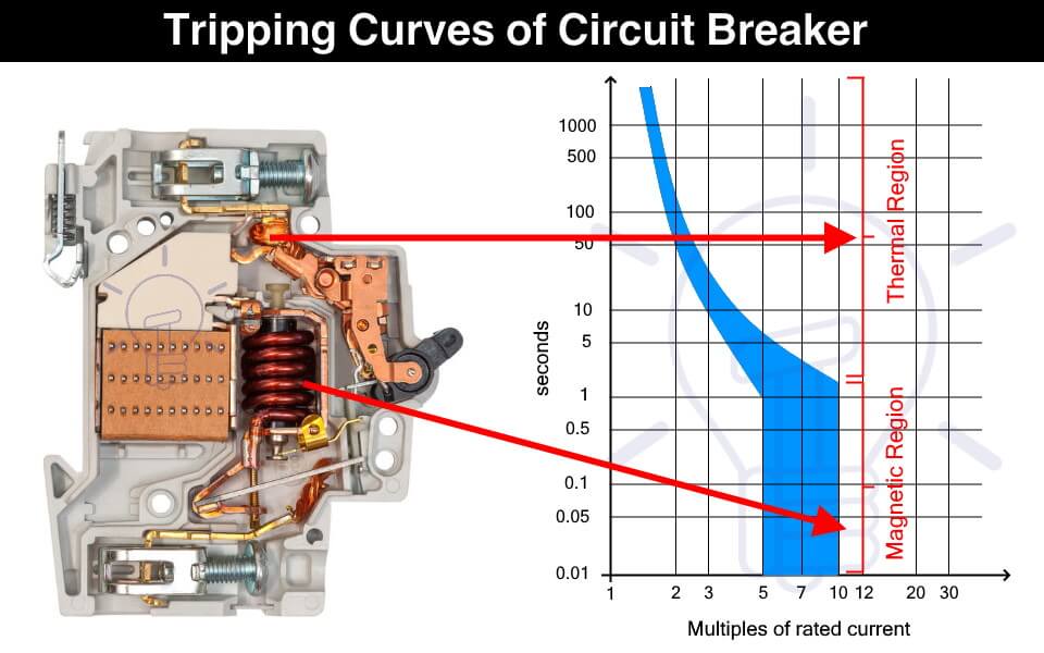
The circuit breaker instantly cut off the power supply to reduce further damage. A circuit breaker has two types of tripping unit i.e. thermal and magnetic tripping unit.
Thermal Tripping Unit: the thermal tripping unit is used for protection against overloading. It uses a bi-metallic contact that bends with a change in temperature. The current flowing through the bimetallic strip heats up contact & trip the circuit breaker.
The rate of bending of the bi-metallic strip depends on the amount of current. Therefore, greater the overloading current, faster the circuit breaker trips.
Magnetic Tripping Unit: The magnetic trip unit is used for protection against short circuit current. it includes a solenoid that produced a strong magnetic field due to high short circuit current to instantly trip the circuit breaker.
Related Posts:
- MCB (Miniature Circuit Breaker) – Construction, Working, Types & Applications
- MCCB (Molded Case Circuit Breaker) – Construction, Types & Working
What is a Trip Curve?
A trip curve also known as a current time graph is a graphical representation of the response of a circuit breaker. It shows the current relationship with the tripping time of a protection device.
Why We Need Different Tripping Curves?
Circuit breakers are used for tripping the power supply as quickly as possible in case of overcurrent. But it should not trip so fast & unnecessary that it becomes a problem.
The overcurrent can happen under normal conditions such as the inrush current of a motor. Inrush current is the huge current draw during the starting of a motor that causes voltage dips in the main line. The circuit breaker should be able to tolerate the inrush current & it should provide some delay before tripping.
Therefore, the circuit breaker selected should not trip so fast that it creates a nuisance & it should not trip so late that it causes any damage. This is where the tripping characteristics of the circuit breakers come into play.
The tripping curve tells how fast a circuit breaker will trip at a specific current. The different tripping curves classify the circuit breakers into categories where each category is used for specific types of loads. It is essential to select a circuit breaker that provides the necessary overcurrent protection.
- Types of Circuit Breakers – Working and Applications
- Air Circuit Breaker (ACB): Construction, Operation, Types and Uses
How to read a Trip Curve?
The following figure shows a chart of a trip curve.
The horizontal X-axis represents the multiples of the current flowing through the circuit breaker. While the Y-axis represents the tripping time of the circuit breaker on a logarithmic scale.

The thermal region shows the response of the bimetallic contact trip unit during overcurrent. The curve shows that the circuit breaker’s tripping time reduces with an increase in the current. The first curve in the graph shows the response of a thermal trip unit.
While the magnetic region shows the response of the solenoid to fault current such as a short circuit current.
As seen from the graph, a circuit breaker does not have a fixed tripping time and we cannot predict an exact tripping point. It is because the tripping is affected by ambient conditions such as temperature. Think of it as a Schrödinger’s Cat area, we do not know when the tripping will occur unless the event happens.
Types of Circuit Breaker Based on Tripping Curves
The circuit breakers are classified into the following five types based on their tripping curves.

Such type of circuit breaker is designed to instantly trip when the operating current is 3 to 5 times its rated current. Their tripping time falls between 0.04 to 13 seconds. They are suitable for domestic applications where surges are very low such as lighting & resistive loads.

They are sensitive and must not be used in places where the normal surges keep on tripping it unnecessarily.
Type C circuit breaker trips instantly at current surges 5 to 10 times its rated current. its tripping time lies between 0.04 to 5 seconds. As they can tolerate higher surge currents, they are used in commercial applications such as the protection of small motors, transformers, etc.

Type D circuit breaker trips instantly when operating current reaches 10 to 20 times its rated current. Its tripping time is 0.04 to 3 seconds. Such circuit breakers can tolerate the high inrush current of large motors. Therefore, they are suitable for running heavy loads in industrial applications.

Such type of circuit breakers trips at 10 to 12 times its rated current with a tripping time of 0.04 to 5 seconds. These circuit breakers are also used for heavy inductive loads in industrial applications.

Type Z circuit breakers are the most sensitive circuit breaker that instantly trips when the operating current reaches 2 to 3 times its rated current. They are used for sensitive equipment that requires very low short circuit trip settings.

- Main Difference between Fuse and Circuit Breaker
- Difference Between MCB, MCCB, ELCB and RCB, RCD or RCCB Circuit Breakers
- How to Read MCB Nameplate Data printed on it?
- How to Find the Proper Size of Circuit Breaker? Breaker Calculator and Examples
- HVDC Circuit Breaker – Types, Working and Applications
- Can We Use AC Circuit Breaker for DC Circuit and Vice Versa?
- Electronic Circuit Breaker – Schematic and Working
- Smart WiFi Circuit Breaker – Construction, Installation and Working
- Why Circuit Breaker Capacity Was Rated in MVA and Now in kA and kV?
- How to Wire 120V and 240V Main Panel? Breaker Box Installation – US – NEC
- How to Wire Single-Phase, 230V Consumer Unit (Breaker Box) with RCD? IEC, UK and EU
This Post has been published by WWW.ELECTRICALTECHNOLOGY.ORG.
Electrical Technology
Related articles.

A Complete Guide About Solar Panel Installation. Step by Step Procedure with Calculation & Diagrams

How to Calculate the Battery Charging Time & Battery Charging Current – Example

Automatic UPS / Inverter Connection Diagram to the Home Panel Board

How to Find the Proper Size of Wire & Cable: Metric & Imperial Systems

Automatic Street Light Control Circuit using LDR & Transistor BC 547

Emergency LED Light Circuit – DP-716 Rechargeable 30 LED’s Lights Schematic
One comment.
Do we have to consider the tripping curves for DIY installation?
Leave a Reply Cancel reply
Your email address will not be published. Required fields are marked *

ELECTRICAL CLASSROOM
A complete Electrical Engineering portal
MCB Trip Curves – B, C, D, K, and Z trip curves
MCB (Miniature circuit breaker) is a re-settable device designed to protect a circuit from short circuits and overcurrents. The trip curve of an MCB (B, C, D, K, and Z curves) tells us about the trip current rating of Miniature Circuit breakers. The trip current rating is the minimum current at which the MCB will trip instantaneously. It is required that the trip current must persist for 0.1s.
Class B trip curve
Class c trip curve, class d trip curve, class k trip curve, class z trip curve, class a trip curve, importance of mcb trip curve types, trip curves for other circuit breakers.
The MCB trip curves, also known as I-t tripping characteristic consist of two sections viz, overload section and short circuit section. Overload section describes the trip time required for various levels of overload currents and the short circuit section describes the instantaneous trip current level of MCB.
Read More: Miniature Circuit Breaker (MCB) – Principle of operation
The MCB with class B trip characteristics trips instantaneously when the current flowing through it reaches between 3 to 5 times the rated current. These MCBs are suitable for cable protection.
MCB with class C trip characteristics trips instantaneously when the current flowing through it reaches between 5 to 10 times the rated current. Suitable Domestic and residential applications and electromagnetic starting loads with medium starting currents.
MCB with class D trip characteristics trips instantaneously when the current flowing through it reaches between Above 10(excluding 10) to 20 times the rated current. Suitable for inductive and motor loads with high starting currents.
MCB with class K trip characteristics trips instantaneously when the current flowing through it reaches between 8 to 12 times the rated current. Suitable for inductive and motor loads with high inrush currents.
MCB with class Z trip characteristics trips instantaneously when the current flowing through it reaches between 2 to 3 times the rated current. These types of MCBs are highly sensitive to short circuits and are used for the protection of highly sensitive devices such as semiconductor devices.

MCB with class A trip characteristics trips instantaneously when the current flowing through it reaches between 2 to 3 times the rated current. Like Class Z MCBs, these are also highly sensitive to short circuits and are used for the protection of semiconductor devices.
MCBs with trip curve class B and trip curve class C is the most commonly used ones. MCBs with Class C trip curves can be found in the lighting power distribution boards in residential and commercial buildings. It trips as soon as the current rises between 5 to 10 times its rated current. Class B MCBs are used in the protection of electronic devices such as PLC, DC power supplies, etc. in control panels. It trips as soon as the current rises between 3 to 5 times its rated current.
In some applications, frequent current peaks occur for a very short period (100ms to 2s). For such applications, class Z-type MCBs shall be used. Class Z-type MCBs are used in circuits with semiconductor devices.
It is important to choose an appropriate MCB current rating and trip curve in order to safeguard the circuit from damage during faults. Hence it is necessary to calculate the short circuit current and inrush current before choosing an appropriate MCB rating. If the chosen MCB rating is much higher than required, then it may not trip in the event of a fault. Similarly, if the MCB is underrated, then it may cause nuisance trips, for example even the starting currents or inrush currents may trip the MCB.
External selection tool: https://new.abb.com/low-voltage/solutions/selectivity/tools-support/curves
All circuit breakers, such as MCCB, ACB, VCB, etc have their own trip characteristics. The only thing is that may not follow the categorization as that of MCB. Also, the circuit breaker curve types are not the same for all types of circuit breakers. It varies from one circuit breaker type to the other and depends on many design factors.
Learn more about MCB:
- What is an MCB?
- Miniature Circuit Breaker (MCB) – Principle of operation
- What is kA rating of MCB and MCCB?
Related Articles: 1. Difference between MCB and MCCB 2. Difference between contactors and relays 3. Difference between Soft Starters and VFDs 4. Difference between MCCB and RCCB 5. Difference between MCB and RCBO 6. Difference between RCCB and RCBO 7. Difference between MPCB and MCCB
27 thoughts on “MCB Trip Curves – B, C, D, K, and Z trip curves”
Very good explanation. I understood the concept. Thank you.
Thank you, Mr. Sanket. Kindly browse through our articles. Please subscribe or follow us on twitter/facebook for instant updates.
Thankhs google team good explace thanks again
Very good mcb make , what Amps load trip make
Very good. Nice explain.. Good job
Explanation is good but your second paragraph doesn’t match the charts. It looks like it is the B-curve that trips between 3-5 times its rated current, and C-curve that trips between 5-10 times its rated current.
Very good, thanks
very good …..thanks
Thanks very much
Very good explanation
Is this curves is applicable to Rccb ?
No. These curves are applicable for mcbs only.
Thanks for your information
The information about mcb is very useful and helpful for a technician, many many thanks for sharing your information.
Great information, I got to know a few more details out of what I wanted to know.
Which type is better choice for UPS protection?
The explanations are very good but in the video is a mistake at minute 0.38. The short circuit sections with the overload section are reversed.
Good for selection of MCB’s
On the c type Mcb on the time curves at a short circuit fault current at 220amp it shows dis connection at 6/7seconds are you saying that disconnection will be instant at this current or 6/7 seconds.
I use B-curve in my home when short circuit occured in the appliace MCB tripped but my appliance burned. My appliance lead wires were shorted by a metal piece was lying on it.I thought MCB could have protected but not. And I also headed big noise of it.
Sorry to hear that. This could be because the MCB was oversized: Much higher than the rated current of the appliance or the MCB could be faulty. We suggest you replace it with a new one. Make sure that you are choosing the right one.
Thanks for sharing such an informative article about MCB.
sir Type C is used for average current load. Type B and C are the most commonly used in DBs. Tripping of MCB Type C is 5-10 times higher than normal. eg: if a 6A mcb put in acircuit , the rated current is 6 A , then how ever the type c mcb with stand 5 to 10 times higherr than normal .
hello, what about the CL curve mcb, because in my home installation I used the cl4 code on the mcb
Perhaps you are referring to product name of the MCB and not its trip curve.
The information is quite educative. Thank you so much
Leave a Comment Cancel reply
IMAGES
VIDEO
COMMENTS
The time for which the OL should pause before reacting will be different for various motors and applications is called the motor trip class. The most common trip classes are 5, 10, 20, and 30, which refer to the number of seconds for which the OL will allow this 600% current in-rush. Applications for each of these trip classes can be classified ...
Issue: Meaning of Trip Classes for overload relays. Product Line: NEMA Overload Relays Environment: North American Products Resolution: The trip class means that at 600% (6 times) of the maximum thermal current rating (or 600% of the actual dial setting on adjustable overloads) the Class 10 will trip in 10 seconds or less, Class 20 will trip in 20 seconds or less, and Class 30 will trip in 30 ...
The trip class corresponds to the value of the tripping time for a current of 7.2 x Ir according to IEC/EN 60947-4-1 standard. The following table shows the value of the tripping time depending on the current in the load for all three classes: Current in the load. Tripping time (in seconds) Class 5. Class 10. Class 20. 1.5 x Ir. 96-120.
What is the trip Class of overload relay? The time taken by them to open the contactor during overloads is specified by the trip class. It is commonly classified into Class 10, Class 20, Class 30, and Class 5. The OLR trips in 10 seconds, 20 seconds, 30 seconds, and 5 seconds respectively at 600% of full load current to the motor.
Quite often we here of applications in which the motor protection/overload relay 'trips' during normal motor starting. The remedial action taken by many when faced with this problem is to select and install a replacement overload relay, generally one that provides a higher 'Trip Class' setting, for example, Trip Class 20 in lieu of the standard Trip Class 10.
Overload Relay Trip Class. The trip class specifies how long it takes them to open the contactor during overloads. Observe the table below from Schneider: Class 10, Class 20, Class 30, and Class 5 are the most popular classifications. At 600 percent of full load current to the motor, the OLR trips in 10 seconds, 20 seconds, 30 seconds, and 5 ...
Class 10 and Class 20 tend to be the most common there is also a Class 5 rating and a Class 30. So what does the difference mean? Simply put the Class rating specifies in what amount of time the overload will trip after it is in an over amperage situation. For example, a Class 10 overload will trip in 10 seconds or less (depending on the ...
An unmarked overload relay is always Class 20. Typical NEMA-rated overload relays are Class 20, but you can adjust many of them about 15% above or below their normal trip current. IEC relays are usually Class 10, and you can usually adjust them to 50% above their normal trip current. When replacing overload heaters, always replace the entire set.
In North America the NEMA Standard MG-1 defines 4 types of Classes as the most common: 5, 10, 20 & 30. Class 5, 10, 20 & 30 overload relays will trip within 5, 10, 20 & 30 seconds respectively at 600% of motor full load amps. Class 5 is usually used for motors requiring extremely fast tripping. Class 10 is commonly used to protect artificially ...
condition. The most common trip classes are Class 10, Class 20, and Class 30. A Class 10 overload relay, for example, has to trip the motor offline in 10 seconds or less at 600% of the full load amps (which is usually sufficient time for the motor to reach full speed). Many industrial loads, particularly high inertia loads, require Class 30.
Conforming to IEC 60947-4-1 and IEC 60947-6-2, the meaning of the tripping class is that the relay will trip in how much time at 7.2 times of rated current. Class 10A 10 20 30
Class 10 4 - 10 sec 1.2 Ie 7.2 Ie Class 20 6 - 20 sec Class 30 9 - 30 sec TA25DU trip class 20 for contactors A9 … A40 and (T) AL9 … (T) AL30 TA25DU1.8-20 1SAZ211401R1025 1.3 … 1.8 6 1 $ 63 TA25DU2.4-20 1SAZ211401R1028 1.7 … 2.4 10 1 TA25DU3.1-20 1SAZ211401R1031 2.2 … 3.1 10 1 TA25DU4.0-20 1SAZ211401R1033 2.8 … 4.0 15 1
The trip classes describe time intervals within which the overload relays have to trip with 7.2 times the set current Ie from the cold state for symmetrical three-pole loads. The tripping times are as follows for: Overload relay tripping times. Tripping characteristic CLASS 10. Tripping characteristic CLASS 10 (SOURCE: Siemens)
The motor trip current does not determine the choice of trip class. Trip class specifies the length of time it will take for the relay to open in an overload condition. Classes 5, 10, 20 & 30 are the most common. Class 5, 10, 20 & 30 overload relays will trip within 5, 10, 20 & 30 seconds respectively at 600% of motor full load amps.
Posted October 8, 2003. The simple explanation is "class 10" will trip within 10 seconds of locked rotor condition. "Class 20" will trip within 20 seconds of locked rotor condition. "Class 10" should be the standard selection. If your application requires longer motor run up time you can use the "class 20".
Common applications, used as a guide to determine appropriate Trip Class. Application. Trip Class. Start Time (s) Notes. Standard. 5. 5. Suitable for Star / Delta applications with < 5 s Star time, motor starts off load.
Common applications, used as a guide to determine appropriate Trip Class. Trip Class 30 4-29: 691 (5/Hr) 55A 30KW 40HP 66A 37KW 50HP 80A 45KW 77HP 97A 55KW 75HP 132 A 160 A 195 A 75 KW 90 KW 110 KW 106 HP 150 HP 175 HP Ie (A) 400V Inline KW 400V Inline HP 460V Trip Class 5 3-5: 355 (10/Hr) (Standard) Trip Class 10B 3.5-12: 708 (5/Hr) Trip Class ...
Class 10/20 (Selectable): Replacement SSOLR for Retrofit of Square D Type S Starter Solid-State Overload Relay 600 Vac Maximum. Locate 8536 Starter in this column. Order Class 9065 Overload Relay from this column. NEMA Size [1] Full Load Current Range (A) Open Type. Trip Class 10/20. 00B [2] 1.5-4.5.
Location. San Francisco Bay Area, CA, USA. Occupation. Electrical Engineer. Nov 14, 2018. #3. The "Class" number is, to make it simple, the amount of time it will take to trip at Locked Rotor Current of 600% of the setting. So Class 10 is 10 seconds, Class 20 is 20 seconds, Class 30 is 30 seconds.
A circuit breaker has two types of tripping unit i.e. thermal and magnetic tripping unit. Thermal Tripping Unit: the thermal tripping unit is used for protection against overloading. It uses a bi-metallic contact that bends with a change in temperature. The current flowing through the bimetallic strip heats up contact & trip the circuit breaker.
interchangeable trip unit. 10 - FRAME SIZE: a term applied to a group of circuit breakers of similar physi-cal configuration. Frame size is expressed in amperes and corresponds to the largest ampere rating available in the group. The same frame size
Description. out the world. Thermal overload relays are 3 pole. The motor current flows through their bimetals (1 per phase) which are indirectly heated. Under the effect of the heating, the bimetals bend, cause the relay to trip and the position of the auxiliary contacts to change. The relay setting range is graduated in amps.
MCBs with trip curve class B and trip curve class C is the most commonly used ones. MCBs with Class C trip curves can be found in the lighting power distribution boards in residential and commercial buildings. It trips as soon as the current rises between 5 to 10 times its rated current.